
Service Steering & Brakes
Adjusting Front Caster Spindle Bearing
NOTE: Adjustment required only if front caster wheel shimmies during travel.
1. Park machine safely. (See Parking Safely in the SAFETY section.)
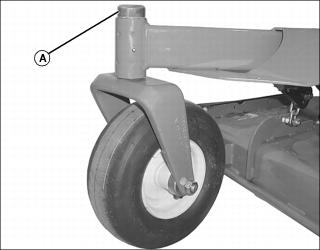
2. Remove dust cover (A) from top of spindle.
4. Turn castle nut 1/4 turn clockwise.
5. Replace cotter pin. Do not loosen the castle nut to align cotter pin hole, increase the tightening to align.
7. Test machine to determine if shimmy is still present. Repeat adjustment as necessary.
Checking and Aligning Motion Control Levers
Check Alignment:
1. Park machine safely. (See Parking Safely in the SAFETY section.)
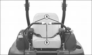
2. Move both motion control levers (A) forward.
3. Check levers for equal alignment.
• Check gap (B) between the levers. The recommended gap is 3–6 mm (1/8–1/4 in.).
NOTE: If the ends of the levers strike against each other while in the neutral position, move the levers to the neutral lock position and carefully bend them outward. Move them back to the neutral position and check for the recommended gap of 3–6 mm (1/8–1/4 in.).
• If positions of the control levers are unequal, an adjustment is necessary.
Alignment Procedure
1. Adjust position of motion control levers:
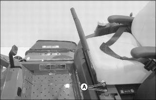
• Slide both levers forward or rearward to desired position on control arm until levers are aligned.
Adjusting Park Brake
1. Park machine safely. (See Parking Safely in the SAFETY section.)
2. Lift rear of machine with a safe lifting device.
3. Verify that the park brake is locked.
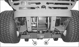
4. Locate the park brake adjustment assembly (A and B) on each side of the machine.
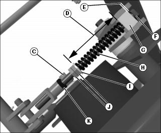
Picture Note: As viewed from top
5. Measure the distance (E) from the swivel block (G) and the head of the brake rod (F).
• Distance (E) should be 3–3.5 mm.
6. If necessary, adjust distance (E).
• Loosen jam nut (K) directly below yoke.
• To obtain distance (E), rotate the rod counter-clockwise using a wrench on jam nuts (J) until the head of the rod protrudes 3–3.5 mm.
• Tighten jam nut (K) against yoke.
7. Measure the length (D) of linkage spring (H).
• The length of compressed spring between the washer (I) and the swivel block (G) should be 82 mm (3 1/4 in.).
8. If necessary, adjust length of linkage spring (H).
• Loosen two hex jam nuts (J).
• Adjust position of two hex jam nuts (J) until the proper distance (D) is obtained.
• Tighten two hex jam nuts (J).
9. Check park brake linkage on other side of machine for proper adjustment.
10. Lock and unlock the park brake four times, then check the dimensions of the brake rods and linkage springs. Repeat steps 4 - 8 as necessary.