
Operating
Daily Operating Checklist
o Make sure all necessary guards and shields are safely and securely attached. Check for loose, missing, or damaged parts.
o Remove mower deck belt shields. Clean grass and debris from belt area.
o Remove grass and debris from machine and mower deck.
o Remove grass and debris from operator’s platform, air intake screen, engine cooling fins, hydraulic pumps, engine compartment and muffler area.
o Check engine and hydraulic oil levels.
o Check all belts for damage or cracking.
o Adjust cutting height if necessary.
o Check wheel bolt torque. Tighten if necessary.
o Check tire air pressure. Check tires for damage or cracking.
o Check and adjust steering control linkages.
o Lubricate front caster spindles/wheels, if equipped.
o Mulch-On-Demand Mower Deck: Lubricate (see label on mower deck).
Avoid Damage to Plastic and Painted Surfaces
• Do not wipe plastic parts unless rinsed first.
• Insect repellent spray may damage plastic and painted surfaces. Do not spray insect repellent near machine.
• Be careful not to spill fuel on machine. Fuel may damage surface. Wipe up spilled fuel immediately.
Operator Station Controls
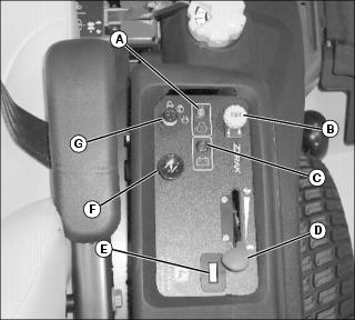
Miscellaneous Controls
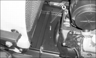
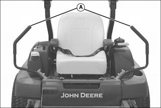
A - Free-Wheeling Pump Release Valves
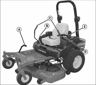
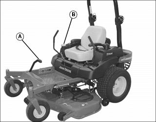
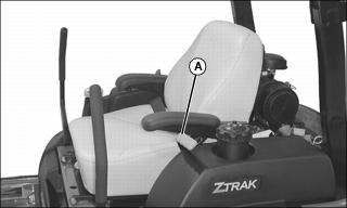
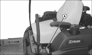
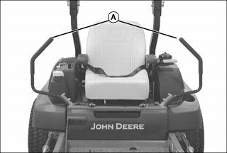
Mounting and Dismounting Machine Safely
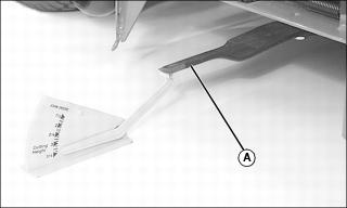
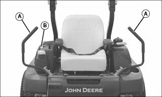
Do not step on either side of the mower deck when mounting and dismounting the machine. Mount the machine from the front using foot plate (A). Park machine safely (See Parking Safely in the SAFETY section.) before dismounting.
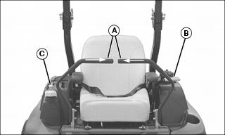
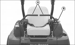
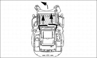
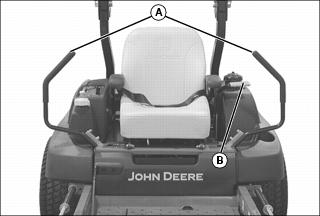
Raising and Lowering Operator Seat
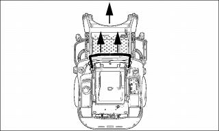
Raising the Seat
1. Park machine safely. (See Parking Safely in the SAFETY section.)
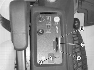
2. Raise up on seat latch (A) to release. Hold latch released while lifting seat.
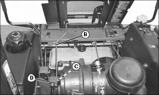
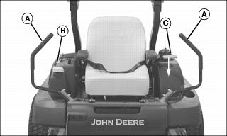
3. Lift seat. Stop rod (B) will travel in slotted frame hole (C).
4. When seat is fully raised, make sure stop rod tab (D) securely locks the seat in the raised position.
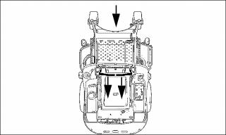
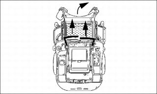
Lowering the Seat
1. Stand on the left side of the machine.
2. Move operator seat slightly forward and lift stop rod (B).
3. Slowly lower seat. Stop rod (B) will travel in slotted frame hole (C).
4. Ensure seat latch is engaged.
Adjusting Seat
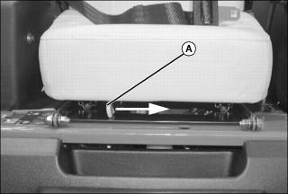
2. Push and hold the seat adjustment lever (A) toward the middle of the seat.
3. Slide forward or backward to desired position.
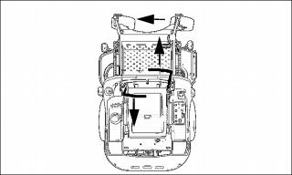
Lowering ROPS
1. Park machine safely. (See Parking Safely in the SAFETY section).
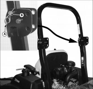
2. Remove spring pin (A) from drilled pin (B) on left and right sides of ROPS.
3. Remove drilled pin from left and right sides of ROPS.
NOTE: ROPS mid-lock position is for MCS equipped machine.
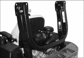
4. Pull ROPS rearward to lower.
5. Install drilled pins and spring pins back into holes in ROPS to secure in place.
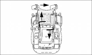
Raising ROPS
1. Park machine safely. (See Parking Safely in the SAFETY section.)
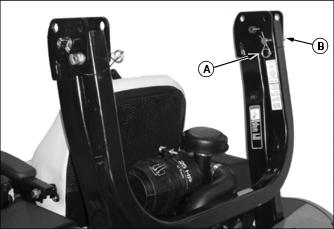
2. Remove spring pin (A) from drilled pin (B) on left and right sides of ROPS.
3. Remove drilled pin from left and right sides of ROPS.
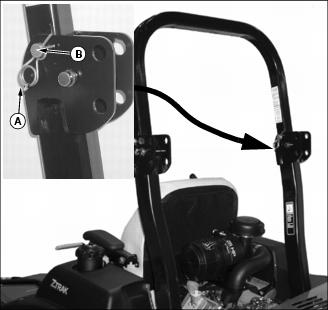
4. Push ROPS into upright position.
5. Install drilled pins (B) into holes on left and right sides of ROPS, and secure in place with spring pins (A).
6. Tighten ROPS mounting hardware to 120 N•m (90 lb-ft).
Adjusting Mower Deck Cutting Height
• The mower deck height adjustment consists of fifteen different cutting heights. The fifteen cutting heights range from 38–127 mm (1-1/2–5 in.) in 6.3 mm (1/4 in.) increments.
• Cutting height levels can be adjusted without leaving the operator seat.
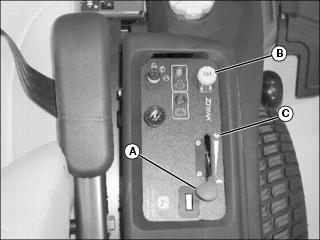
Cutting Height Adjustment Procedure
1. Park machine safely. (See Parking Safely in the SAFETY section.)
3. Stop engine and lock park brake.
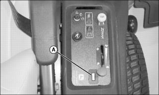
4. Step on the deck lift pedal (A) and hold it down.
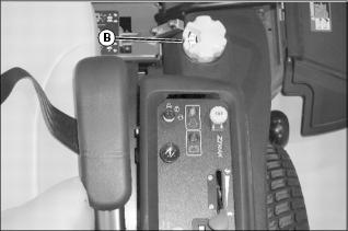
5. Turn height-of-cut knob (B) to the desired setting.
Leveling Mower Deck
NOTE: Mower deck anti-scalp wheels should not contact the ground.
1. Park machine safely. (See Parking Safely in the Safety section.)
2. Inflate tires to the correct pressure.
3. Step on deck lift pedal and turn height-of-cut knob to the transport position.
• The transport position is the 127 mm (5 in.) cutting height position.
Checking Level (Side-to-Side)
NOTE: Mower deck anti-scalp wheels should not contact the ground.
1. Step on deck lift pedal and turn height-of-cut knob to the 76 mm (3 in.) cutting height position.
NOTE: Discharge chute raised to illustrate photo clarity.
2. Position left mower blade in the sideways (left to right) position.
NOTE: Use a short ruler or a leveling gauge to check the mower blade level.
3. Measure from outside blade tip to the ground.
4. Position right mower blade (A) (discharge side) in the side-to-side position.
5. Measure from outside blade tip to the ground.
• The difference between both measurements should be no greater than 3 mm (1/8 in.).
6. If side-to-side level is not within the given tolerance, an adjustment is necessary.
Adjusting Level (Side-to-Side)
1. Step on deck lift pedal and turn height-of-cut knob to the transport position.
• The transport position is the 127 mm (5 in.) cutting height position.
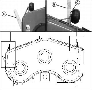
2. Place 76 mm (3 in.) wood blocks (B) under each side of the mower deck.
• The wood block placed under the left side of the mower deck must be positioned to the rear of the raised portion of the deck wall.
NOTE: The right front anti-scalp wheel must not rest on the wood block.
• The wood block placed under the right side of the mower deck must be positioned under the right front anti-scalp wheel bracket (C).
3. Lower mower deck down onto the wood blocks.
4. Step on deck lift pedal and turn height-of-cut knob to the 83 mm (3-1/4 in.) cutting height position.
5. Remove mule belt from clutch.
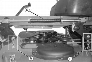
6. Loosen lift assist springs (D) on each side of machine to allow deck to sit flat.
7. Verify that cam follower located on rear lift shaft is in contact with height adjustment cam on lift system.
8. Adjust front and rear chain lengths (E) on each side of machine so there is no slack in links and deck is freely supported by the 76 mm (3 in.) wood blocks.
9. Step on deck lift pedal and turn height-of-cut knob to the transport position.
• The transport position is the 127 mm (5 in.) cutting height position.
10. Remove wood blocks from under both sides of the mower deck.
11. Step on deck lift pedal and turn height-of-cut knob to the 76 mm (3 in.) cutting height position.
12. Check side-to-side mower level. Repeat adjustment as needed.
Checking Level (Front-to-Rear)
1. Step on deck lift pedal and turn height-of-cut knob to the 76 mm (3 in.) cutting height position.
2. Position right mower blade (discharge side) in the straight forward (front-to-rear) position.
3. Measure from the right front blade tip to the ground.
4. Turn blade 180? and measure from right rear blade tip to the ground.
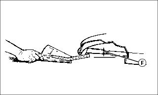
• The height (F) of the rear blade tip should be between 3 - 6 mm (1/8 - 1/4 in.) higher than the front blade tip.
5. If the front-to-rear level is not within the given tolerance, an adjustment is necessary.
Adjusting Level (Front-to-Rear)
NOTE: Adjust side-to-side mower level before adjusting front-to-rear level.
Adjust both sides of the mower deck equally.
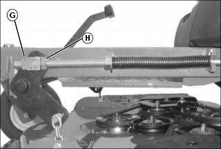
1. Loosen jam nut (G) on each deck lift assist rod.
2. While positioned in front of the machine, adjust mower level:
• Turn hex nut (H) clockwise to lower front of mower deck.
• Turn hex nut (H) counterclockwise to raise front of mower deck.
3. Verify that the adjustment on right and left sides is equal.
5. Check front-to-rear mower level.
6. Install mule belt when all adjustments are made.
Adjusting Deck Lift Spring Tension
NOTE: Deck lift spring tension is adjusted at the factory. If the effort required to raise or lower the mower deck is not satisfactory, an adjustment may be necessary.
Check Spring Tension
1. Park machine Safely. (See Parking Safely in the SAFETY section.)
2. Stop engine and lock park brake.
3. Step on deck lift pedal and turn height-of-cut knob to the transport position.
• The transport position is the 12.7 cm (5 in.) cutting height position.
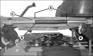
4. Measure distance (A) between the washers (B) on each deck lift spring assembly.
• The recommended factory setting is 28 cm (11 in.).
Adjust Spring Tension
NOTE: Both deck lift spring assemblies must be adjusted equally.
Do not over tension the deck lift springs. If the springs are compressed too tightly, the mower deck will float too freely.
Decrease deck lift spring tension if operating in rough terrain.
While positioned in front of the machine:
• Turn hex nut (C) clockwise to increase deck lift spring tension and reduce the effort to raise and lower the mower deck.
• Turn hex nut (C) counterclockwise to decrease deck lift spring tension and increase the effort to raise and lower the mower deck.
Operating Mulch-On-Demand Mower Deck
Mulch Mode
1. Park machine on a hard level surface.
2. Place motion control levers in the neutral lock position.
3. Pull deck mode lever (A) back until lever locks into the mulch position.
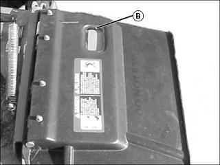
• Window (B) on discharge chute will be clear when operating in the mulch mode.
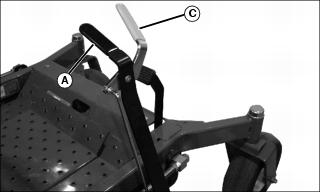
Side Discharge Mode
1. Park machine on a hard level surface.
2. Place motion control levers in the neutral lock position.
3. Pull yellow release lever (C) back to release lock. Spring tension moves deck mode lever forward.
• Window (B) on discharge chute will be orange when operating in the side discharge mode.
Recommended Blades for 60-Inch Mulch-On-Demand Deck
Adjusting Mower Deck Anti-Scalp Wheels
NOTE: The flattest cut can be achieved by having all anti-scalp wheels adjusted off the ground. Check anti-scalp whel adjustments each time the mower deck cutting height is changed.
It is recommended that all anti-scalp wheels be kept off the ground to minimize scuffing.
1. Inflate tire to correct pressure.
2. Adjust mower deck to desired cutting height.
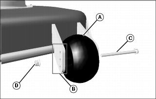
3. Adjust anti-scalp wheel (A) to one of three positions (B).
• Remove cap screw (C) and nut (D).
• Adjust wheel up or down so it is approximately 6-13 mm (1/4-1/2 in.) above mowing surface.
4. Install wheel with attaching hardware.
5. Adjust all wheels to the same height.
Testing Safety Systems

The safety systems installed on your machine should be checked before each machine use. Be sure you have read the machine operator manual and are completely familiar with the operation of the machine before performing these safety system checks.
Use the following checkout procedures to check for normal operation of machine.
If there is a malfunction during one of these procedures, do not operate machine. See your authorized dealer for service.
Perform these tests in a clear open area. Keep bystanders away.
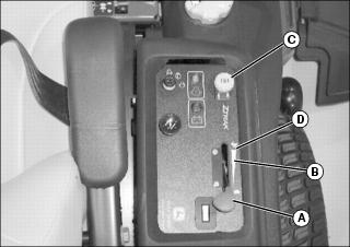
Testing PTO Switch
1. Sit on the operator seat with the motion control levers (A) in the neutral lock position.
3. Pull PTO knob (B) up to engage mower deck.
4. Turn key switch to the start position.
Testing Park Brake Switch
1. Sit on the operator seat with the motion control levers (A) in the neutral lock position.
2. Push PTO knob (B) down to disengage.
4. Turn key switch to the start position.
Testing Neutral Start Switch
IMPORTANT: Avoid damage! Repeat this test three times, with the motion control levers in the following positions: 1. Right side motion control lever inward. |
NOTE: Do not sit on the seat during this test.
1. Move motion control lever(s) (A) inward to the neutral position.
3. Push PTO knob (C) down to disengage.
4. Turn key switch to the start position.
Testing Seat Switch
3. Pull PTO knob up to engage.
4. Rise slightly off the seat.
Testing the Park Brake
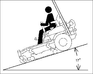
1. Stop machine on a 17 degree slope (30% grade). Stop the engine and lock the park brake.
Using Seat Belt
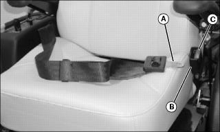
2. Pull out seat belt buckle (A) and stretch across your lap in one nonstop motion.
3. Insert seat belt buckle into latch (B) until it locks.
4. To release seat belt, press red button (C) until buckle comes out of latch.
Using the Park Brake
Locking Park Brake
• Raise park brake lever (A) to lock park brake.
Unlocking Park Brake:
• Lower park brake lever (A) to unlock park brake.
Using the PTO Knob
Engage PTO:
1. Move throttle lever (A) to the 1/2 to 3/4 fast position.
2. Pull PTO knob (B) up to engage mower deck.
3. Move throttle lever (A) forward to the fast position (C) for mowing.
Disengage PTO:
Using the Throttle Lever
• Push throttle lever (A) all the way forward to the fast position (D) when mowing.
• Move throttle lever (A) to the half throttle position (C) when starting and warming the engine.
• Pull throttle lever (A) to rear to slow position (B) to idle engine. Do not run engine at slow idle any longer than necessary.
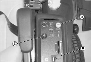
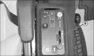
Using the Hour Meter
NOTE: The machine is equipped with an electric start. The hour meter will continue to run with the key switch left in the run position.
• The hour meter (A) shows number of hours the machine has run.
• The service interval chart gives necessary service intervals. Use the hour meter and service interval chart to determine when machine will need service.
Using the Motion Control Levers
The functions of the motion control levers are:
• Dual function neutral position.
Neutral Lock Position
• Motion control levers (A) must be in the neutral lock position and the park brake locked to start the engine.
• Forward and reverse movement of the motion control levers is prevented when levers are moved to the neutral lock position.
• Operator can exit mower with the engine running when the PTO switch is disengaged, the motion control levers are in the neutral lock position and the park brake is locked.
• Motion control levers must be in the neutral lock position to safely enter and exit the operator seat.
Neutral Position
• Machine speed, motion, and direction can be controlled when the engine is running, motion control levers are in the neutral position, and the park brake is unlocked.
Forward and Reverse Motion:
1. Move throttle lever to the fast position.
3. Move both motion control levers from the neutral lock position inward to the neutral position.
4. Push the control levers forward to begin forward motion.
• The further forward the control levers are moved, the faster the machine will travel.
• Forward speed range:0–14.5 km/h (0–9.0 mph).
5. Pull both control levers rearward at the same time to begin reverse motion.
• Reverse speed range: 0–6.4 km/h (0–4 mph).
6. To stop motion, move both motion control levers forward or rearward until the machine comes to a stop.
NOTE: The motion control linkages are adjustable. If adjustment is required see Checking and Adjusting Motion Control Linkages in the Service Transmission section.
Forward:
• Push both motion control levers forward at the same time.
Reverse:
• Pull both control levers past center rearward at the same time.
Gentle Left Turn:
• Push right control lever further forward than the left control lever.
Gentle Right Turn:
• Push left control lever further forward than the right control lever.
Sharp Left Turn:
• Push right control lever forward and pull left control lever rearward at the same time.
Sharp Right Turn:
• Push left control lever forward and pull right control lever rearward at the same time.
Starting the Engine
1. Move both motion control levers (A) to the neutral lock position.
2. Sit on the operator’s seat.
4. Push the PTO switch knob (C) down to disengage the PTO.
5. Move throttle lever (D) to set engine speed:
• Cold engine: Pull knob up to the choke position.
• Warm/Hot engine: If necessary, pull knob up to the choke position.
7. Turn key switch to the start position (F).
8. Release key to the run position (G) when the engine starts.
• Push choke knob to the off position.
• Move throttle lever to the fast position.
Engaging Mower
2. Move throttle lever (A) to the 1/2–3/4 throttle position (B).
4. Move both motion control levers to the neutral position.
5. Pull PTO knob (C) up to engage mower deck.
6. Move throttle lever to the fast position (D).
7. Push motion control levers forward slowly. Mow at a safe travel speed.
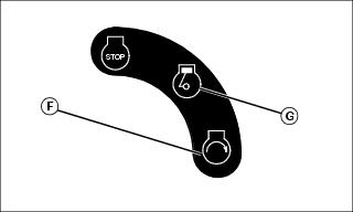
Stopping the Engine
1. Move the motion control levers (A) to the neutral lock position.
3. Move throttle lever to the 1/2 fast position (B).
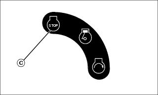
4. Turn key switch to STOP position (C).
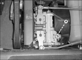
Using the Free-Wheeling Pump Release Valves
IMPORTANT: Avoid damage! Transmission damage may occur if the machine is towed or moved incorrectly: |
NOTE: The free-wheeling pump release valves must be turned fully clockwise (closed) during normal vehicle operation.
When the machine needs to be moved without starting the engine, use the free-wheeling pump release valves:
2. Lift and secure operator seat platform in the raised position.

3. Loosen the jam nut on each free-wheeling valve using a 17 mm wrench. Use an 8 mm wrench to turn both free-wheeling pump release valves (A) counterclockwise approximately 1/4 turn.
6. Push machine to desired location. Due to hydraulic system drag, machine will move slowly.
IMPORTANT: Avoid damage! The bypass valves can be damaged if overtightened. Use care not to overtighten. |
7. To return to service, tighten both free-wheeling valves to 6.9 N•m (61 lb-in.). Tighten jam nuts to 19.6 N•m (173 lbin.).
Transporting Machine
IMPORTANT: Avoid damage! Transmission damage may occur if the machine is moved or towed incorrectly: |
Use a heavy-duty trailer to transport your machine. Trailer must have signs and lights required by law.
1. Step on deck lift pedal and turn height-of-cut knob to the transport position.
• The transport position is the 127 mm (5 in.) cutting height position.
2. Drive machine onto a trailer.
3. Stop engine and lock park brake.
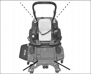
5. Fasten machine to trailer with heavy-duty straps, chains, or cables. Both front and rear straps must be directed down and outward from machine as shown.
Mowing Tips
• Mow grass with throttle lever in the full fast / mow position.
• Keep mower deck and discharge chute clean.
• Properly level mower deck for a smooth cut.
• Use a travel speed that fits the conditions:
• Mow tall or wet grass twice. Cut grass at half desired height – then cut at desired height.
• Travel slow when mowing tall, thick or wet grass.
• Avoid damaging grass by slipping or skidding machine drive wheels. Practice smooth control lever movements.
• When performing sharp turns, do not allow inside machine drive wheel to stop and twist on grass.
Mowing Travel Speeds
• Normal mowing on level ground.
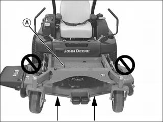
Dismounting to Inspect Mower
1. Park machine on a hard, level surface.
2. Push knob down to disengage PTO.
3. Move motion control levers to the neutral lock position.
5. Stop engine and remove key. Wait for mower blades to stop turning before leaving operator’s seat.