
Service Transmission
Transmission and Hydraulic Oil
IMPORTANT: Avoid damage! Machine is filled with John Deere HY-GARD™ (J20C) Transmission/Hydraulic Oil at the factory. DO NOT mix oils. DO NOT use type “F” automatic transmission fluid |
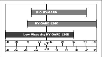
Use oil viscosity based on the expected air temperature range during the period between oil changes.
John Deere J20C HY-GARD Transmission/Hydraulic Oil is recommended. John Deere J20D Low Viscosity HY-GARD Transmission/Hydraulic Oil may also be used.
Use John Deere BIO HY-GARD™ oil when a biodegradable fluid is required.
Other oils may be used if they meet John Deere standard JDM J20C or J20D.
Biodegradable Oil
Application
When use of a biodegradable lubricant is desired or required, BIO HY-GARD is recommended. BIO HY-GARD may be used under normal mowing conditions.
DO NOT USE biodegradable lubricants in machines for the following operations:
• Any machine used for scalping procedure.
• Any verticut operation in temperatures exceeding 32?C (90?F).
• Mixing of biodegradable oil and mineral oil will reduce the biodegradability of the lubricant in the machine. Mixing of HY-GARD and BIO HY-GARD will not result in performance deterioration.
Cold Weather Operation
Precautions should be taken if BIO HY-GARD containers or equipment are stored for long periods of time in extremely cold temperatures. Freezing should be expected if BIO HY-GARD is subjected to the following temperatures:
• Stored for six months at -18? to -23?C (-1? to -10?F)
• Stored for seven days at -23? to -26?C (-10? to -15?F)
• Stored for three days at -26? to -29?C (-15? to -20?F)
• Stored for two days at -29? to -34?C (-20? to -30?F)
• Stored for one day at -34?C (-30?F) and below.
IMPORTANT: Avoid damage! Equipment should not be started or any operation attempted until BIO HY-GARD™ has reached a safe operating viscosity. |
If freezing of BIO HY-GARD is suspected, the container or equipment MUST be warmed to at least 0?C (32?F) and maintained for 24-48 hours to ensure the fluid has reached a safe operating viscosity.
Converting From HY-GARD to BIO HY-GARD
Systems being converted from HY-GARD to BIO HY-GARD should follow the procedure listed below to obtain maximum lubricant biodegradability.
1. Park machine on a level surface.
2. Lower cutting units, stop engine, set park brake and remove key from ignition.
5. Fill reservoir with BIO HY-GARD to appropriate level.
6. Start engine and bring to medium idle.
7. Turn steering wheel full stroke several times and cycle cutting units several times.
8. Stop engine and check hydraulic oil level. Add BIO HY-GARD to appropriate level.
9. Operate machine under normal operating conditions for a minimum of two hours.
11. Follow recommended maintenance schedules.
Checking Hydrostatic Drive Oil Level
1. Park the machine safely. (See Parking Safely in the SAFETY section.)
2. Check oil level when oil is cold.
NOTE: Ensure main hydraulic reservoir is 100% full before checking fluid level on dipstick.
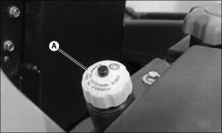
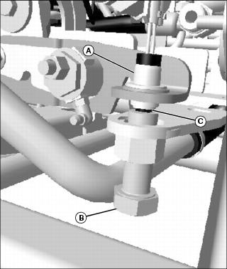
3. Remove hydraulic oil fill cap (A) and pull dipstick out to check oil level.
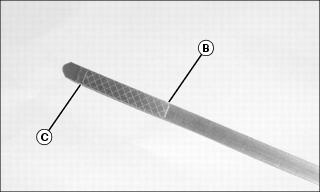
4. Oil level should be between “full” line (B) and “add” line (C).
5. If oil level is low, add John Deere HY-GARD™ oil or an equivalent. If oil level is too high, drain appropriate amount of oil.
6. Install hydraulic oil fill cap.
Changing Hydrostatic Drive Oil
IMPORTANT: Avoid damage! Clean area around plugs before removing to prevent dirt and other contaminants from entering oil reservoir. |
1. Park the machine safely. (See Parking Safely in the SAFETY section.)
NOTE: Drain plug is located at left rear of machine, below fuel tank.

2. Remove plug (A) and drain oil into a drain pan with at least a 22.7 L (6 gal) capacity.
3. Install plug. Tighten to 9.5 •m (7
4. Fill reservoir with approximately 20.8 L (5.5 gal) of oil. Use John Deere HY-GARD™ oil or an equivalent oil meeting John Deere specifications.
Picture Note: Seat shown removed for picture clarity.
• Fill main hydraulic reservoir to 100% capacity.
• Install fill plug. Tighten to 27 •m (20
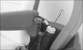
• Fill secondary hydraulic reservoir through hydraulic oil fill cap (C) to proper level.
5. Start the engine. Cycle hydraulic controls and turn steering wheel back and forth for approximately 2 minutes.
6. Stop the engine and check oil level. Add oil as necessary.
Cleaning Hydraulic Oil Reservoir Strainer
NOTE: Clean the hydraulic oil reservoir strainer when changing the hydraulic oil and filter. Service the strainer when the hydraulic oil reservoir is empty.
1. Change hydraulic oil and filter.
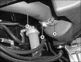
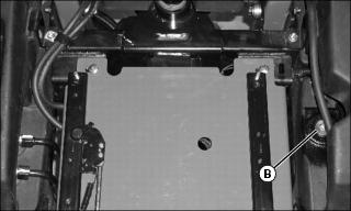
2. Locate hydraulic oil reservoir strainer (A) under left side of machine.
3. Loosen adjustable hose clamp (B).
NOTE: Use drain pan to catch dripping oil.
4. Remove rubber hose (C) from strainer.
5. Loosen and remove strainer from reservoir housing.
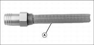
6. Clean strainer (A) with solvent or mineral spirits.
8. Apply thread sealant to strainer threads.
9. Install strainer into reservoir housing and tighten to 27-34 N•m (20-25 lb-ft).
10. Install rubber hose (C) onto strainer.
11. Install and tighten adjustable hose clamp (B).
Cleaning Mow-Backlap Valve Screen
1. Park the machine safely. (See Parking Safely in the SAFETY section.)
2. Allow hydraulic oil to cool.
3. Raise hood and locate mow-backlap valve at left side of machine.
NOTE: Use drain pan to catch dripping oil.
4. Remove hose and fitting from “P” port (A).
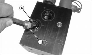
6. Clean screen with solvent or mineral spirits.
7. Install screen in “P” port and tighten securely.
9. Check oil level. Add oil as necessary.
Replacing Hydrostatic Drive Oil Filter
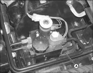
1. Park the machine safely. (See Parking Safely in the SAFETY section.)
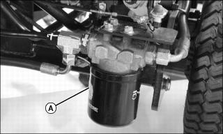
2. Turn hydraulic oil filter (A) to the left (counterclockwise) to remove. Use drain pan to catch dripping oil.
3. Put a film of clean oil on seal of new filter.
4. Tighten filter until it contacts mounting surface. Tighten filter one full turn after gasket contact. A filter wrench may be required.
5. Start the engine and check for leaks.
6. Stop engine and check hydraulic oil level. Add oil as necessary.
Adjusting Transmission Neutral Creep
NOTE: The machine may creep forward or backward while in neutral position with engine running. If so, an adjustment is needed.
NOTE: Neutral start switch adjustment must be performed after this procedure has been completed.
1. Park machine on a level surface.
3. Lift machine with a suitable lifting device just high enough to allow drive wheels to turn.
4. Support machine with stable supports.
5. Operate lift control and allow cutting units to settle on the ground.
6. Before making any adjustment, perform a thorough visual inspection of linkages and return springs for damage; repair or replace as necessary.
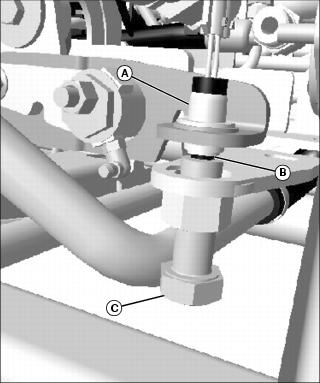
7. Locate transmission neutral switch (A) and ensure that switch plunger (B) is not “bottoming out.” Adjust hex head bolt (C) accordingly.
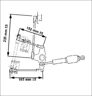
8. Check transmission link to ensure that it is 235 mm (9.252 in. rod end. If not, adjust.
9. Set forward pedal link at 152 mm
10. Set reverse pedal link at 185 mm
11. Start engine and run at slow idle.
12. With an operator in the operator’s seat, lock the park brake.
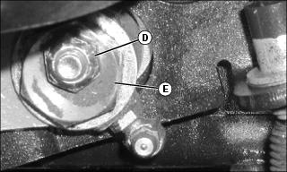
13. Loosen eccentric locknut (D).
14. Rotate eccentric (E) forward or backward until drive wheels stop turning; tighten eccentric locknut while holding eccentric in position.
15. Have the operator depress the drive pedals in both directions and release.
16. Drive wheels should stop turning when pedals are released; if not, repeat adjustment.
17. Adjust reverse pedal link until reverse pedal lines up with forward pedal.
Adjusting the Neutral Start Switch
NOTE: Transmission neutral creep adjustment should be performed before this adjustment is made.
Before performing this procedure test neutral start switch for proper operation.
Testing Neutral Start Switch
1. Park machine on a level surface.
3. Lift machine with a suitable lifting device just high enough to allow drive wheels to turn.
4. Support machine with stable supports.
5. Operate lift control and allow cutting units to settle on the ground.
6. Start engine and run at slow idle.
Adjusting the Neutral Switch
1. Park machine on a level surface.
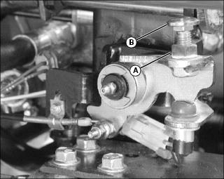
4. With engine off turn bolt (B) until it lightly presses the plunger (C).
NOTE: If engine fails to start, tighten bolt so it presses more on the plunger and start engine.
6. Repeat test procedure to ensure that engine stops in the first inch of pedal travel.
7. When switch is properly set, remove machine from jack stands.
Adjusting Mow-Transport Cable
1. Park the machine safely. (See Parking Safely in the SAFETY section.)
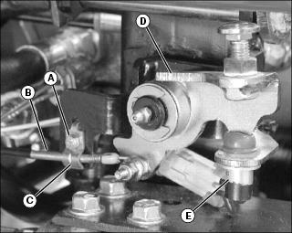
2. Loosen hex head bolt and locknut (A) until mow-transport cable (B) can be repositioned under cable clamp (C).
3. Adjust cable so that mow speed limiting cam (D) depresses plunger and closes mow switch (E) when mow-transport lever is in the mow position.
4. Tighten hex head bolt and locknut.
Adjusting Mow Ground Speed
1. Loosen jam nut (A) and adjust carriage bolt (B) up or down to adjust mow speed.
• Lengthening the bolt reduces mow speed.
• Shortening the bolt increases mow speed.
2. Tighten jam nut after mow speed adjustment has been made.