
Service Steering & Brakes
Removing and Installing Rear Drive Wheels
Removing:
1. Park machine safely. (See Parking Safely in the SAFETY section.)
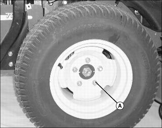
2. Slightly loosen five wheel nuts (A).
3. To remove the rear drive wheels on the machine:
· Lift machine with a safe lifting device.
Installing:
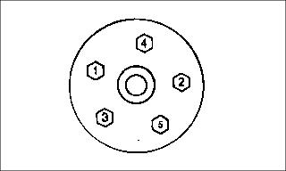
2. Install and tighten wheel nuts in numbered sequence shown for safe wheel installation. Tighten alternately until recommended torque value is reached.
· Tighten nuts to 100 N·m (75 lb-ft.).
Removing and Installing Front Caster Wheels
Removing
1. Park machine safely. (See Parking Safely in the SAFETY section.)
2. Lift front of machine with a safe lifting device.
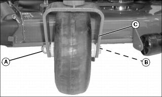
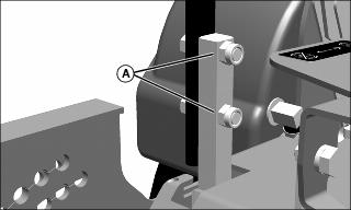
3. Remove hex nut (A) and wheel bolt (B).
4. Remove wheel from assembly yoke (C).
Installing
2. Install wheel bolt (B) and hex nut (A).
Adjusting Front Caster Spindle Bearing
NOTE: Adjustment required only if front caster wheel shimmies during travel.
1. Park machine safely. (See Parking Safely in the SAFETY section.)
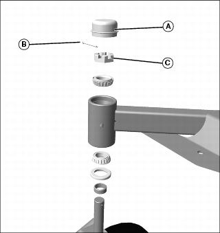
2. Remove dust cover (A) from top of spindle.
4. Turn castle nut (C) 1/4 turn clockwise.
5. Replace cotter pin. Do not loosen the castle nut to align cotter pin hole; increase the tightening to align.
7. Test machine to determine if shimmy is still present. Repeat adjustment as necessary.
Checking and Aligning Motion Control Levers
Checking Alignment:
1. Park machine safely. (See Parking Safely in the SAFETY section.)
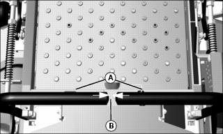
2. With the levers (A) in the neutral position, check the gap (B) between the lever tips.
· The recommended gap is 3-6 mm (1/8-1/4 in.). If the lever end gap is not within specification, move the levers to the neutral lock position and carefully bend them outward. Move them back to neutral position and check for the recommended gap.
3. Move both motion control levers fully forward and check levers for equal alignment.
· If positions of the control levers are unequal, an adjustment is necessary.
Alignment Procedure
2. Slide both levers forward or rearward to desired position on control arm until levers are aligned.
Adjusting Park Brake
1. Park machine safely. (See Parking Safely in the SAFETY section.)
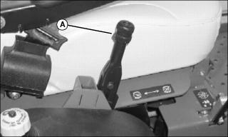
2. Loosen set screw (A) on park brake handle knob and and turn knob clockwise several times. Tighten set screw down into the lower slot.