
Assembly
Parking Safely
1. Stop machine on a level surface, not on a slope.
2. Disengage mower blades or any other attachments.
3. Lower attachments to the ground.
7. Wait for engine and all moving parts to stop before you leave the operator's seat.
8. Close fuel shut-off valve, if your machine is equipped.
9. Disconnect the negative battery cable or remove the spark plug wire (for gasoline engines) before servicing the machine.
Assemble Machine
1. Place pallet on flat, level surface, with enough room to work safely. Remove pallet from work area after dismantling to prevent injuries from falls, nails, and splinters.
2. Remove plastic cover from machine.
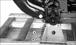
3. Using a floor jack under the front transaxle housing, take the weight off of the front axle until the lug bolts and washers (A) can be removed from the shipping brackets (B).
4. Remove four lug bolts and washers from left and right side of front axle.
5. Remove shipping brackets from left and right side of shipping container.
6. Lift front of machine high enough to install front wheels.
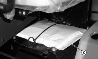
7. Locate bag of parts (C) from operator's seat adjustment lever. Remove bag from machine and take out six lug bolts and six lock washers.
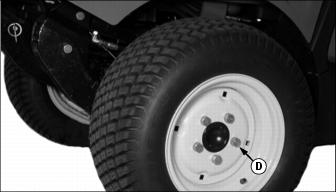
8. Using lug bolts and washers from bag of parts and shipping brackets, install front tires onto front axle and torque bolts to 225 N·m (165 lb-ft).
9. Lower machine off of floor jack.
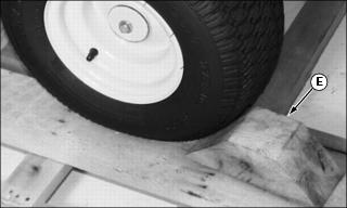
10. Using a pry bar and hammer, remove the wheel blocks (E) from behind the left and right side rear tires.
11. Cut shipping straps holding rear axle to pallet.
12. Drive machine straight off of pallet.
Charge and Connect Battery
1. Remove and discard the red positive (+) protective cap from the positive (+) battery terminal.
· Battery is fully charged at 12.6 volts.
3. Connect positive (+) battery cable to battery.
4. Connect negative (-) battery cable.
5. Apply general purpose grease or silicone spray to terminal to help prevent corrosion.
6. Slide red cover over positive battery cable.
Check Tire Pressure
2. Check tire pressure with an accurate gauge.
3. Check that tires have equal air pressure. Add or remove air, if necessary.
Raise ROPS
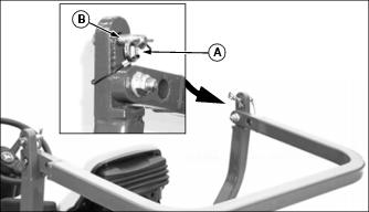
1. Remove spring pin (A) from drilled pin (B) on left and right side of ROPS.
2. Remove drilled pin from left and right side of ROPS.
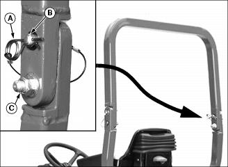
3. Push ROPS into upright position.
4. Install drilled pin (B) into holes on left and right side of ROPS, and secure in place with spring pins (A).
5. Tighten the ROPS attaching bolts (C) to 40 N·m (30 lb-ft).
Checking Engine Oil Level
1. Park machine safely. (See Parking Safely in the SAFETY section.)
2. Tilt operator's seat platform forward.
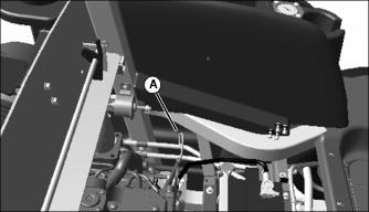
3. Remove dipstick (A) located on the left side of the engine under the seat. Wipe dipstick with a clean cloth.
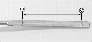
4. Install dipstick, then remove again. Check oil level. Oil should be between levels (B) and (C) on the dipstick.
· If oil is low, add oil to bring oil level no higher than level (B) on the dipstick.
· If oil is above level (B) on the dipstick, drain to proper level.
6. Lower operator's seat platform.
Test Safety Systems

The safety systems installed on your machine should be checked before each machine use. Be sure you have read the machine operator manual and are completely familiar with the operation of the machine before performing these safety system checks.
Use the testing procedures in the Operating section of this manual to check for normal operation of machine.
If there is a malfunction during one of these procedures, do not operate machine. See your authorized dealer for service.
Perform these tests in a clear open area. Keep bystanders away.
Testing PTO Switch
1. Sit on the seat and verify seat is properly adjusted for operator's weight. (Seat should spring down slightly so seat switch is actuated.)
3. Pull PTO knob up to the ON position.
5. Unlock the park brake (keep the PTO switch on). Try to start engine.
Testing Seat and Park Brake Switch
1. Sit on the seat and verify seat is properly adjusted for operator's weight. (Seat should spring down slightly so seat switch is actuated.)
2. Push PTO knob down to the OFF position.
3. Push down master brake pedal.
5. Release master brake pedal.
6. Rise up off of seat, but do not get off machine.
Testing the Park Brake
1. Stop machine on a 17° slope (30% grade). Stop the engine and lock the park brake.