
Operating Machine
Daily Operating Checklist
o Check engine, transaxle, and 4WD oil levels.
o Remove debris from machine and attachment.
o Check area below machine for leaks.
o Check air restriction indicator.
o Remove debris from radiator, oil cooler, and alternator.
o Check brakes and forward and reverse pedals.
Avoid Damage to Plastic and Painted Surfaces
· Do not wipe plastic parts unless rinsed first.
· Insect repellent spray may damage plastic and painted surfaces. Do not spray insect repellent near machine.
· Be careful not to spill fuel on machine. Fuel may damage surface. Wipe up spilled fuel immediately.
· Prolonged exposure to sunlight will damage the hood surface.
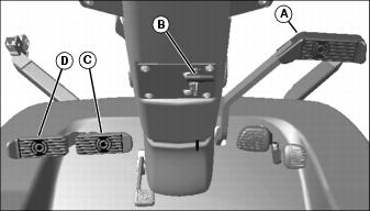
Operator Station Controls
B - Choke Lever (Model 1420 Only)
C - Engine Coolant Temperature Lamp
D - Hydraulic Oil Temperature Lamp
E - Engine Manifold Heater Lamp (Diesel Only)
G - Material Collection System Lamp
H - Power Take-Off Indicator Lamp
A - Steering Column Tilt Lock Lever
D - Turn Brake Pedal Lock (1545 and 1565 only)
D - Seat Spring Adjustment Knob
E - Seat Spring Weight Indicator

C - 4WD Control Lever (1420, 1435, 1445)
A - 4WD Control Lever (1545 and 1565)
B - Two-Speed Transaxle Shift Lever (1545 and 1565)
A - Seat Height Adjustment Lever
Miscellaneous Controls
Testing Safety Systems

The safety systems installed on your machine should be checked before each machine use. Be sure you have read the machine operator manual and are completely familiar with the operation of the machine before performing these safety system checks.
Use the following checkout procedures to check for normal operation of machine.
If there is a malfunction during one of these procedures, do not operate machine. See your authorized dealer for service.
Perform these tests in a clear open area. Keep bystanders away.
Testing PTO Switch
1. Sit on the seat and verify seat is properly adjusted for operator's weight. (Seat should spring down slightly so seat switch is actuated.)
3. Pull PTO knob up to the ON position.
5. Unlock the park brake (keep the PTO switch on). Try to start engine.
Testing Seat and Park Brake Switch
1. Sit on the seat and verify seat is properly adjusted for operator's weight. (Seat should spring down slightly so seat switch is actuated.)
2. Push PTO knob down to the OFF position.
3. Push down master brake pedal.
5. Release master brake pedal.
6. Rise up off of seat, but do not get off machine.
Testing the Park Brake
1. Stop machine on a 17° slope (30% grade). Stop the engine and lock the park brake.
Using Proper Ballast
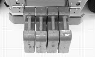
· Attachments used with this machine may require ballast to prevent tipping and loss of control when the attachment is raised.
· Check the attachment operator's manual or see your John Deere dealer for ballasting information.
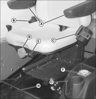
Adjusting Seat
Adjusting Seat Position
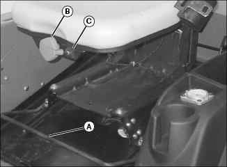
2. Pull seat adjustment lever (A) up, out of locked position.
3. Slide seat forward or rearward to desired position. Operator's right heel should be able to rest firmly on the floor in front of the forward and reverse pedals.
Adjusting Seat Spring Tension
1. Turn seat spring adjustment knob (B) to adjust seat spring tension while watching weight indicator (C).
2. Match weight of operator to value shown in weight indicator. Seat must spring slightly so that operator's presence switch will be actuated, allowing engine to start.
Adjusting Seat Height
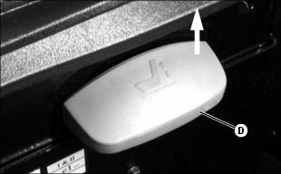
1. Pull up on the front of the base of the seat, and the seat height adjustment lever (D), until the seat height lock disengages.
2. Raise or lower the operator's seat to desired height. (There are four positions available.)
3. Release the seat height lock lever and continue to move the seat slightly until it latches in place.
Using Seat Belt
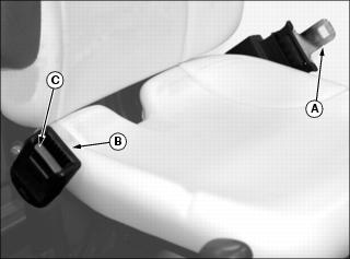
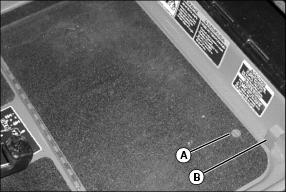
2. Pull out seat belt buckle (A) and stretch across your lap in one non-stop motion.
3. Insert seat belt buckle into latch (B) until it locks.
4. To release seat belt, press red button (C) until buckle comes out of latch.
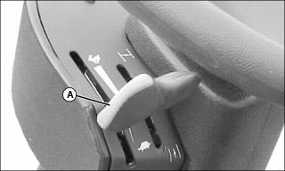
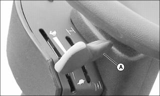
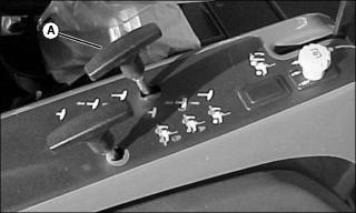
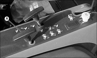
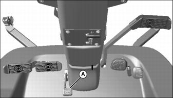
Adjusting Steering Column
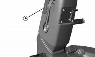
2. Pull lever (A) outward to release steering column.
3. Move steering column forward or rearward to desired position.
4. Push lever back in to lock steering column in place.
Using PTO Knob
The starter will not crank if the PTO is engaged. The PTO will disengage if any of the following conditions exist:
· High engine coolant temperature.
· High hydraulic oil temperature.
· Master brake pedal is depressed.
· To turn PTO off, push PTO knob (A) down.
· To turn PTO on, pull PTO knob up.
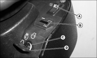
Using Key Switch
NOTE: Starting motor will engage only if the following conditions exist:
· Master brake pedal is depressed.
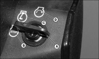
· To turn ignition off, turn the key (A) to the stop position (B).
· To turn ignition on, turn key to the RUN position (C). The beeper will sound, and the following indicator lamps on instrument panel will light:
· Engine Coolant Temperature Lamp
· Engine Manifold Heater Lamp (Diesel Only)
· To start engine, turn key to the START position (D). Once engine begins to run, release key switch back to the RUN position (C). With the key switch in the START position, the following indicator lamps on instrument panel will light:
· Engine Coolant Temperature Lamp
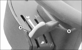
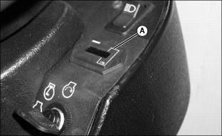
Using Throttle Lever
· Pull the throttle lever (A) to the rear for slow idle. Use this position to start engine and maneuver the mower in confined spaces.
· Push throttle lever fully forward to the FAST IDLE position for transporting and mowing.
Using Choke Lever (1420)
A - Choke Lever (Model 1420 Only)
· Push the choke lever (A) forward to aid in starting the engine when cold.
· Pull the choke lever rearward once engine has started, or when starting the engine when hot.
Opening Engine Cover
1. Park machine safely. (See Parking Safely in the SAFETY section).
2. Engine cover latch must be unlocked before opening engine cover. Insert key in slot (A) and turn counterclockwise to unlock latch. Remove key to prevent damage or loss.
3. Turn the latch handle (B) counterclockwise.
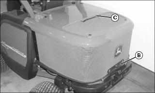
4. Lift up and back on latch handle (B) and pull back on support handle (C).
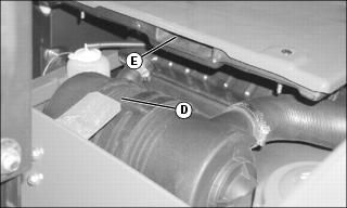
5. To close the engine cover, rotate the cover forward using support handle (C). While lifting cover up and in using latch handle (B), make sure tab (D) goes into slot (E).
6. Rotate latch handle clockwise to latch.
7. To lock the engine cover latch, insert key in slot and turn clockwise.
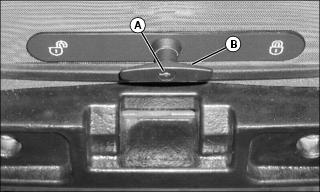
Opening Service Hatch
1. Park machine safely. (See Parking Safely in the SAFETY section.)
2. Unlock service hatch lock (A) by turning 3/4 turn counterclockwise with a large screwdriver.
3. Lift service hatch, using handle (B).
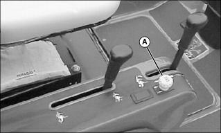
Using Hour Meter
The hour meter (A) records the number of hours the engine has run. Electronic hour meters can be read with key switch in ON position.
Use the hour meter and the service interval chart to determine when service procedures need to be performed on the machine and mower deck.
Using Four Wheel Drive (4WD) (1420, 1435 1445)
· Push 4WD control lever (A) forward (position shown) to use on-demand four wheel drive. Rear wheels will engage whenever front wheel slip is detected, and will disengage automatically. Rear wheels are not driven in reverse.
· Pull 4WD lever rearward to engage full time four wheel drive. Four wheel drive is locked in for forward and reverse travel.
· Traveling forward (slowly) while pulling the 4WD lever rearward helps to engage the 4WD lock.
· Traveling rearward (slowly) while pushing the 4WD lever forward helps to disengage the 4WD lock.
Using Four Wheel Drive (4WD) (1545 and 1565)
· Move the 4WD control lever (A) to the center position to use on-demand (automatic) four wheel drive. Rear wheels will engage whenever front wheel slip is detected, and will disengage automatically or when machine is reversed.
· Twist the 4WD control lever clockwise, and pull up to highest position to disengage 4WD.
· Twist 4WD control lever counterclockwise while pushing down to lowest position to engage full-time four wheel drive. Four wheel drive is locked in for forward and reverse travel.
· Traveling forward (slowly) while pushing the 4WD lever down helps to engage the 4WD lock.
· Traveling rearward (slowly) while pulling the 4WD lever up helps to disengage the 4WD lock.
Using Two-Speed Transaxle (1545 and 1565)
· Pull the two-speed transaxle shift lever (A) up to the highest position to shift the transaxle into the low gear range. This is used to climb hills and drive attachments through thick material.
· Place the two-speed transaxle shift lever in the centered position to shift transaxle into neutral. This position is used to push or tow the machine.
· Push the two-speed transaxle shift lever down to the lowest position to shift the transaxle into the high gear range. This is used for high speed transport and while performing light duty work with the machine.
· Slowly moving the machine with no load while changing gear range helps to engage the gears.
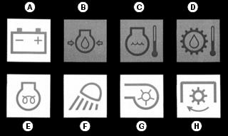
Indicator Lamps
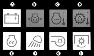
Battery Discharge Lamp (A)
· The battery discharge lamp indicates the battery is not getting enough charge from the alternator. The lamp should illuminate when the key switch is turned to the RUN position, and should turn off once the engine starts.
Engine Oil Pressure Lamp (B)
· The engine oil pressure lamp indicates the engine oil pressure is low. The lamp should illuminate when the key switch is turned to the RUN position, and should turn off once the engine starts. The warning beeper will sound when the lamp illuminates and the PTO will disengage.
Engine Coolant Temperature Lamp (C)
· The engine coolant temperature lamp indicates that the engine is overheating. The lamp should illuminate when the key switch is turned to the RUN position, and should turn off after approximately 5 seconds has elapsed. The warning beeper will sound when the lamp illuminates, and the PTO will disengage.
· If the lamp illuminates while mowing, perform the following steps:
a. Remove foot from hydrostatic pedal to stop travel.
b. Push PTO switch down to OFF position.
d. Set throttle to SLOW IDLE position.
e. If a major coolant leak is seen coming from the engine compartment, stop the engine immediately.
f. If no coolant or steam can be seen leaking from the engine, open the engine cover. Allow engine to idle for 5 minutes, or until coolant temperature light goes off, then stop engine.
· Allow engine to cool. Check and clean area around radiator and hydraulic oil cooler for buildup of debris and grass.
· Fill coolant overflow tank with a 50/50 mix of coolant and water.
· Inspect cooling system for damage and repair. Fill radiator with 50/50 mix of coolant and water.
Hydraulic Oil Temperature Lamp (D)
· The hydraulic oil temperature lamp indicates high hydraulic oil temperature. The beeper will sound and PTO will disengage. Stop machine and allow to idle until lamp turns off.
Engine Manifold Heater Lamp (E) (1435, 1445, 1545, 1565 Only)
· The manifold heater lamp will illuminate to indicate the intake manifold heater is energized and the operator should wait until it turns off before starting the engine.
· The manifold heater is controlled by a temperature sensitive timer, and will turn off sooner in warm weather.
· Starting the engine before the indicator turns off will waste fuel, create smoke, and put unnecessary wear on the starter.
Work Lamp Indicator (F)
· The work lamp indicator will illuminate any time the work lamps on the front of the steering console are turned on.
Material Collection System Lamp (G)
· The material collection system (MCS) lamp will illuminate when the optional MCS PTO switch is engaged.
Power Take-Off Indicator Lamp (H)
· The power take-off lamp will illuminate when the PTO is engaged.
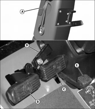
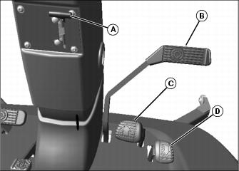
Using Hydrostatic Pedals
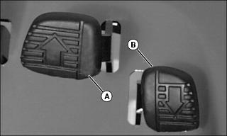
Using the Forward Pedal
1. Push the forward pedal (A) down slightly to begin forward motion. Push the pedal down farther to travel faster.
2. Release the pedal to return to neutral and stop the mower.
Using the Reverse Pedal
Before backing up, carefully check the area around the machine. |
1. Push the reverse pedal (B) down slightly to begin reverse travel. Push the pedal down farther to travel faster.
2. Release pedal to return to neutral and stop the machine.
Using Brakes
Using Master Brake Pedal
NOTE: When the master brake is engaged, the PTO is disengaged.
1. Push the master brake pedal (A) down to hold the machine stationary on a slope, or for an emergency stop. PTO will disengage when master brake pedal is depressed, and PTO switch will have to be recycled once brake is released to restart PTO.
Using Park Brake
1. Lock the park brake by pulling the park brake lock lever (B) upwards and fully depressing the master brake pedal (A). The pedal should stay locked down.
2. Unlock the park brake by depressing the master brake pedal and pushing the park brake lock lever down. Release the master brake pedal.
Using Turn-Brakes
The turn-brakes are used to change direction quickly within the width of the machine. Avoid locking the tire with turn-brake in areas where turf damage is not acceptable. Turn-brakes will not turn machine if traction assist is engaged.
1. Depress the right turn-brake pedal (C) to slow or stop the right front wheel, while power is applied to the left wheel. The machine will turn to the right. Release the turn-brake pedal to resume driving in a straight line.
2. Depress the left turn-brake pedal (D) to turn to the left.
Using Traction Assist Pedal
The traction assist lock is used to help improve traction on slopes and on slippery surfaces. The front drive axle will lock so that the front wheels turn together.
To Lock the Traction Assist
1. Push the traction assist lock pedal (A) down with the left foot and hold it.
To Unlock the Traction Assist
2. The traction assist will stay locked as long as wheel rotation is unequal. Once the load on the transmission is equalized and reduced, the traction assist lock will disengage automatically.
Using Fuel Shutoff Valve (1435)
NOTE: Close fuel shutoff valve when storing machine or when transporting on a trailer.
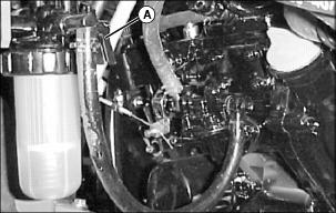
1. Open the engine cover. Locate the fuel shutoff valve (A) on the left side of the engine.
· To open the fuel shutoff valve:
Turn the handle so the pointer is facing up.
· To close the fuel shutoff valve:
Turn the handle so the pointer is facing forward.
Using Fuel Shutoff Valve (1445, 1545, 1565)
NOTE: Close fuel shutoff valve when storing machine or when transporting on a trailer.
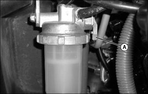
1. Open the engine cover. Locate the fuel shutoff valve (A) on the left side of the engine.
· To open the fuel shutoff valve:
Turn the handle so the pointer is facing up, as shown.
· To close the fuel shutoff valve:
Turn the handle so it is pointing forward.
Raising and Lowering ROPS
Raising ROPS
1. Park machine safely. (See Parking Safely in the SAFETY section.)
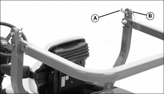
2. Remove spring pin (A) from drilled pin (B) on left and right side of ROPS.
3. Remove drilled pin from left and right side of ROPS.
4. Push ROPS into upright position.
5. Install drilled pin (B) into holes on left and right side of ROPS, and secure in place with spring pins (A).
6. Check the ROPS bolt torque if the ROPS is loose.
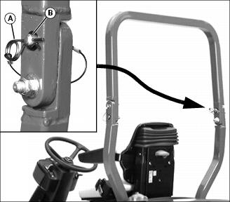
Lowering ROPS
1. Park machine safely. (See Parking Safely in the SAFETY section).
2. Remove spring pin (A) from drilled pin (B) on left and right side of ROPS.
3. Remove drilled pin from left and right side of ROPS.
4. Pull ROPS rearward to lower.
5. Install drilled pins and spring pins back into hole in ROPS to secure in place.
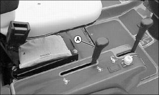
Raising and Lowering the Attachment
1. Turn off PTO. Raising an attachment will not stop the PTO; the attachment continues to run in the raised position.
To Raise Attachment
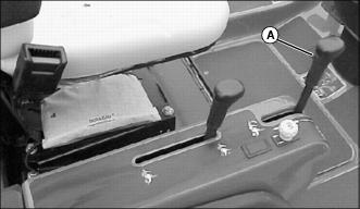
· Pull lift lever (A) rearward. Attachment will rise up until lever is released, or attachment reaches top of travel, whichever occurs first.
To Lower Attachment
· Push lift lever forward. Attachment will lower until lever is released, or attachment reaches the ground, whichever occurs first.
To Float Attachment
· Push lift lever fully forward until it latches into float position. Attachment will rise and lower, as needed, to follow contour of ground.
Starting Engine
NOTE: The engine will not start unless the PTO is off, and the master brake pedal is depressed.
1. Models 1435, 1445, 1545, 1565: Open the fuel shutoff valve.
2. Sit on the operator's seat. (Seat should spring down slightly so seat switch is actuated.)
3. Put on seat belt (if ROPS is not in folded position).
4. Depress master brake pedal if park brake is not locked.
5. Push down the PTO knob to the off position.
6. Pull the throttle lever back to the slow idle position.
7. Model 1420 only: Push the choke lever fully forward if engine is cold, or half-way forward if engine has been run and is still warm.
8. Turn the key to the on position.
9. Models 1435, 1445, and 1545, 1565: Wait for the engine preheat light to turn off.
IMPORTANT: Avoid damage! Do not overheat starter. Do not operate starter more than ten seconds at a time. Wait two minutes before trying again if engine does not start. |
10. Turn the key to the start position for no longer than ten seconds. Release key to run position after engine starts.
· If starter engages, but engine does not start, wait two minutes and try again for no longer than ten seconds.
IMPORTANT: Avoid damage! Do not idle engine for long periods of time. Excessive idling can cause engine overheating, carbon build-up, and poor performance. |
11. Let engine run at half-speed position for two minutes to allow it to warm up before operating machine.
12. Model 1420: Pull choke lever fully back before operating.
Stopping Engine
1. Push PTO switch down to the OFF position.
2. Move throttle lever back to the SLOW IDLE position. Let engine run at slow idle a few seconds.
4. Lower attachment to the ground.
5. Turn the key switch to STOP position.
NOTE: Model 1420 only: The engine will continue to run for 1-2 seconds after key is turned to the OFF position. This is normal and prevents build-up of unburned gas in the exhaust system.
Transporting Machine
1. Push PTO switch down to the off position.
2. Lower the attachment to the ground.
3. If necessary to transport with the attachment raised, avoid hard braking and slopes, and keep transport speeds low.
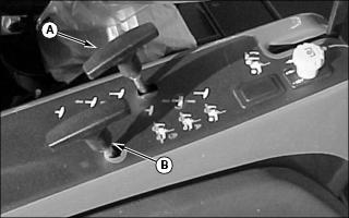
Moving Machine with Engine Off
IMPORTANT: Avoid damage! Transmission damage may occur if the machine is moved or towed incorrectly: |
1. Turn key switch to OFF position.
1420, 1435, 1445
1. Push 4WD lever into FORWARD position.
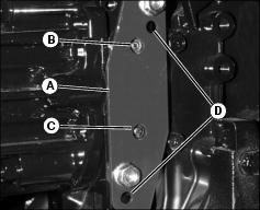
2. Open service hatch and locate the red plate (A) on the right side of the transaxle housing.
· For pushing machine short distances in the forward direction, push in and release the top relief valve (B) with a small tool.
· For pushing machine short distances in the reverse direction, push in and release the bottom relief valve (C) with a small tool.
· For pushing machine longer distances in forward and reverse, remove the two M8 flange head nuts and install plate to lower set of drilled holes (D). Install nuts.
5. Push machine slowly by hand, or using winch, using brakes when necessary.
6. Do not use another vehicle to push or tow mower at high speed.
7. If red plate was moved to the lower set of holes, move it back to original position.
1545 and 1565
1. Push 4WD lever down into 2WD position.
2. Place two-speed transaxle shift lever to centered neutral position.
4. Push machine slowly by hand or using winch, using brakes when necessary.
Transporting Machine on Trailer
Be sure trailer has all the necessary lights and signs required by law.
2. Drive forward onto heavy-duty trailer with attachment raised.
3. Lower attachment down to platform of trailer.
4. Stop engine, remove key, lock park brake.
5. Close the fuel shutoff valve (diesel model only).
6. Fasten machine to trailer with heavy-duty straps, chains, or cables. Fasten rear straps to rear frame or axle. Fasten front straps around front transaxle. Both front and rear straps must be directed down and outward from machine.
7. Check that engine cover is closed and latched. Fold ROPS to avoid overhead clearance problems while on trailer.
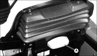
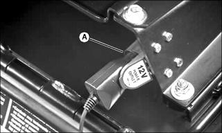
Using Power Outlet

The power outlet provides 12 volts direct current (VDC) to power accessories. It is fused at 10 amps and powered regardless of ignition switch position. The outlet has a weather resistant spring-loaded cover. Always unplug devices and close cover before storing machine.