
Operating - Cutting Units
Cleaning Cutting Units
1. Clean cutting units daily after use.
2. Wash grass clippings from cutting units using low-pressure water.
3. Grease cutting units with proper grease.
Engaging Cutting Units
IMPORTANT: Avoid damage! Run engine at full throttle so cutting units can operate at correct speed. Rear cutting units lower to ground and rise after front cutting units. |
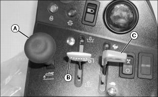
1. Push lift-lower lever (A) forward to lower cutting units.
2. Move the mow-transport lever (B) to mow, to engage cutting units. Cutting units will begin to engage when lowered.
NOTE: With the mow-transport lever engaged, the lift-lower lever needs only to be pushed down or pulled back all the way and not held, to lower or raise the cutting units.
With the mow-transport lever back to the transport position, the lift-lower lever needs to be held back all the way until the cutting units rise to transport height.
3. To begin mowing, pull the lift-lower lever (A) back to the lift position.
4. Move the throttle lever (C) fully forward to the fast idle position.
5. Slowly begin forward travel.
NOTE: The four-wheel drive system (optional) engages when the mow-transport lever is in the mow position. If you disengage the mow-transport lever, the four-wheel drive system disengages.
6. Push lift-lower lever (A) forward to lower cutting units and start reel rotation.
· Front cutting units lower to the ground before the rear units.
NOTE: With the mow-transport lever in the mow position, the two cutting units on the front wings can no longer lift all the way up. They lift just enough to allow for turning.
7. As soon as the first cutting unit reaches the opposite edge of the fairway, pull back the lift-lower lever.
· The cutting units will rise to mow lift height and automatically turn off.
NOTE: If the cutting units were raised before moving the mow-transport lever to the transport position, the cutting units will need to be lowered and then raised to reach transport position.
8. When finished mowing, move the mow-transport lever (B) to transport position to disengage the cutting units. Hold lift-lower lever back to raise the cutting units to transport position.
IMPORTANT: Avoid damage! If equipped with turbocharger, run engine at slow idle for 2 minutes to allow turbocharger to cool down before stopping engine. |
9. Stop machine and let engine run for a short time to cool down engine.
Adjusting Reel Speed
IMPORTANT: Avoid damage! It is recommended to use the highest speed necessary to avoid marcelling. Reduced reel speed may help reduce bed knife and reel wear. |
1. Park fairway mower on a hard, level surface.
2. Stop engine and lock park brake.
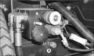
3. Locate reel speed control knob (A) on the left side of machine.
NOTE: Variances in reel speed may occur when knob settings are equal. Use a reel tachometer to verify that the front and rear reels are turning at the same speed for the same knob settings.
· Reel speed can be adjusted depending on the type of application for the fairway mower, which type of cutting units are used, and grass height and conditions.
· It may be appropriate to reduce reel speed when cutting taller grass to prevent grass from being blown over and not being cut. Faster reel speeds with dry grass may cause grass clippings to be thrown over the grass catcher.
· For mowing fairways, set the speed control knob (A) to the highest setting fully to the left (counterclockwise) for best cutting performance.
· For mowing roughs, reel speed may be reduced by turning the speed control knob to the right (clockwise).
Adjusting Bed Knife-to-Reel (2500M)
IMPORTANT: Avoid damage! When adjusting bed knife-to-reel, lower and raise the bed knife evenly. Do not adjust more than one flat on the adjuster nut at a time, alternating side to side. |
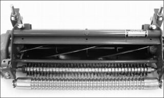
1. Remove cutting reels from machine.
2. Position cutting unit on workbench as shown.
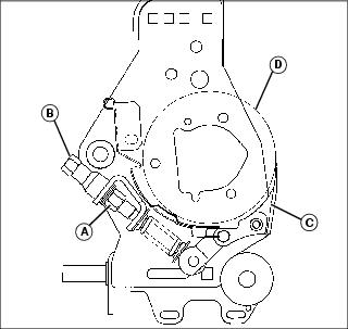
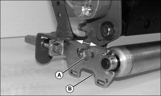
3. On both sides of cutting unit, loosen jam nut (A) and turn bed knife tower adjuster (B) counterclockwise until bed knife (C) is tight against cutting reel (D).
4. Slowly tighten tower adjuster (B) clockwise, alternating from side to side until bed knife (C) begins to pull away from the cutting reel. Cutting reel should rotate freely.
NOTE: Make sure that the final adjustment to the bed knife is pulling the bed knife away from the cutting reel.
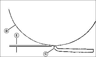
5. With the use of a feeler gauge, alternately turn adjusters (B) no more than one flat at a time until bed knife to reel clearance (E) measures 0.025 mm to 0.050 mm (0.001 in. to 0.002 in.).
6. Tighten jam nuts (A). Check the bed knife-to-reel clearance (E). Adjust again if necessary.
Adjusting Height-of-Cut Range (2500M)
Adjust front roller brackets for the height of cut (HOC) range desired.
· Select height-of-cut (HOC) adjustment range by adjusting the position of both front roller brackets.
· Alignment of roller bracket (A) and cutting unit frame adjustment holes (B) on each side of the cutting unit will determine the HOC adjustment range.
· Refer to chart for desired setting.
NOTE: For heights of cuts greater then 19 mm (3/4 in.), replace the rear HOC adjustment bolts with two M10 x 70 bolts.
Adjusting Front Roller Parallel with Bed Knife (2500M)
NOTE: Use of a bench plate or a two- or three-bolt height-of-cut gauge bar is recommended when adjusting front roller parallel with the bed knife.
Always adjust bed knife-to-reel before adjusting front roller for parallelism.
Always make parallelism adjustment after adjusting front roller height of cut range.
Parallelism Adjustment with Bench Plate
1. Position cutting unit upright on flat surface or workbench.
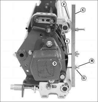
2. Loosen hex nut (A) and hex nut (B) on the left roller bracket.
3. Set bench plate (C) on a level surface. Set cutting unit on top of bench plate. Bed knife (D) must rest firmly against plate stop (E) with cutting reel blade (F) on top of plate stop.
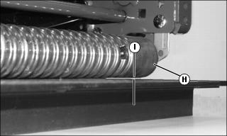
4. Rotate eccentric adjuster (G) until the front roller (H) sits flat and parallel with the bench plate. Gap (I) should not exceed 0.050 mm (0.002 in.) maximum.
5. Tighten left roller bracket hex nut (A).
6. Tighten left roller bracket hex locknut (B).
Parallelism Adjustment with HOC Gauge Bar
1. Position cutting unit upright on flat surface or workbench.
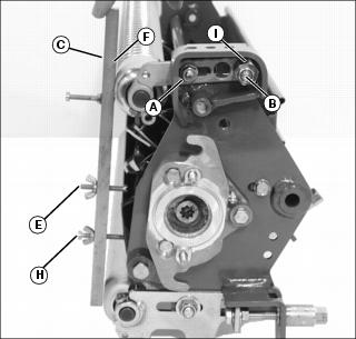
2. Loosen hex nut (A) and hex nut (B) on the left roller bracket.
NOTE: HOC gauge bar should not contact the bottom of the rear roller.
3. Rest HOC gauge bar (C) approximately 51 mm
(2 in.) from the right end of the bed knife (D).
4. Hook the center gauge screw (E) on the edge of the bed knife. Hold end of gauge bar against the bottom of front roller (F).
5. Loosen wing nut (G). Turn lower gauge screw (H) clockwise until top of screw makes contact with flat edge of bed knife.
NOTE: HOC gauge bar should not contact the bottom of the rear roller.
7. Rest HOC gauge bar (C) approximately 51 mm
(2 in.) from the left end of the bed knife (D).
8. Hook the center gauge screw (E) on the edge of the bed knife. Hold end of gauge bar against the bottom of front roller (F).
9. Adjust position of front roller.
· Rotate eccentric adjuster (I) until top of lower gauge screw (H) makes contact with the bed knife.
10. Tighten left roller bracket hex nut (A).
11. Tighten left roller bracket hex locknut (B).
12. Check adjustment using HOC gauge bar.
Adjusting Height-of-Cut (2500M)
1. Position cutting unit upright resting on the rear roller brackets.
2. On both sides of rear roller, loosen locknut (A) just enough for the height-of-cut (HOC) bracket (B) to slide.
NOTE: If machine is equipped with the optional rear roller powered brush, the idler gear pivot locknut and pivot bracket locknuts must be loosened.
3. On the height-of-cut (HOC) gauge bar, set center adjustment bolt head (C) at the desired height-of-cut (D). Lock wing nut (E).
4. Rest HOC gauge bar against front roller (F) approximately 51 mm (2 in.) from the end of the bed knife. Set the inside of the bolt head (G) against the edge of the bed knife.
5. Turn tower adjuster (H) until the rear roller (I) contacts the HOC gauge bar. Repeat for the other side of the cutting reel.
NOTE: If machine is equipped with optional rear roller power brush, the idler gear pivot locknut and pivot bracket locknuts must be tightened after HOC adjustment.
6. Check HOC adjustment setting from side to side and adjust if necessary. Tighten locknut (A) on both sides of cutting unit.
Adjusting Cutting Unit Shield (2500M)
NOTE: Keeping the shield close to the cutting blades improves the performance of the grass catcher in most conditions.
1. Loosen two bolts (A) and locknuts on each side of cutting unit.
2. Raise or lower shield (B) to desired position.
· Maintain an approximate 1.5 mm (0.06 in.) clearance between the bottom of the shield and the top of the cutting blades.
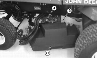
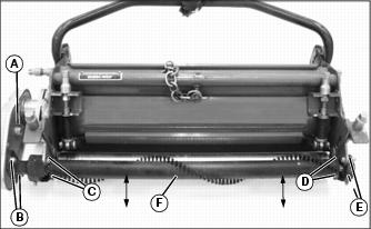
Removing and Emptying Grass Catchers (2500M)
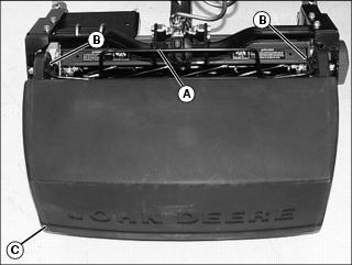
Picture Note: Top photo shows grass catcher installed onto the frame assembly.
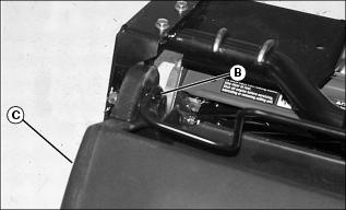
1. Pull back on the release catch hook (A).
2. Lift and remove basket (C) from left-side catcher bracket support hook (B).
3. Remove basket (C) from right-side catcher bracket support hook (B) and empty.
4. Install grass catcher onto the frame assembly.
Adjusting Height-of-Cut After Servicing (22 ESP)
NOTE: The following procedure is to be used for initial setup, HOC fine tuning or after servicing the cutting unit. For quick field adjustments, see Height-of-Cut Field Adjustment in this section.
1. Raise cutting units to Rotate for Service (RFS) position.
2. Shut off engine and lock park brake.
3. Adjust reel-to-bed knife before adjusting HOC.
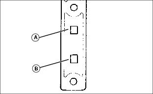
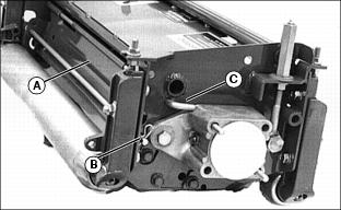
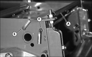
4. Adjust Height-of-Cut Range:
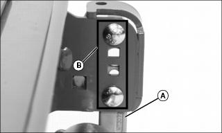
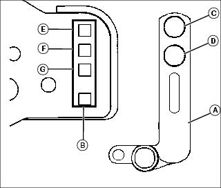
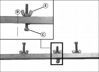
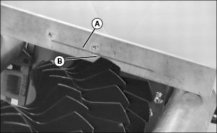
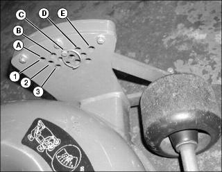
NOTE: Height-of-cut has two general height settings: 9.525 mm to 41.275 mm (3/8 in. to 1-5/8 in.) and 38.1 mm to 88.9 mm (1-1/2 in. to 3-1/2 in.). Adjusters must be installed with carriage bolt in top hole (A) (stud end) for HOC lower than 38.1 mm (1-1/2 in.), and the bottom hole (B) for HOC greater than 38.1 mm (1-1/2 in.).
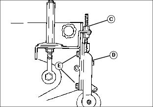
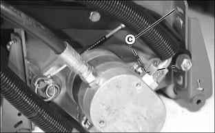
· If HOC range needs to be changed, loosen nut (C). Remove nut and washer (D) and two bolts (E) and position the carriage bolt in the correct hole for the cutting height range desired.
NOTE: Using a single-bolt adjusting gauge bar will not ensure parallelism between rollers and may result in uneven height-of-cut. If rollers are adjusted to a position so gauge bar cannot be installed, raise either the front or rear roller or both to allow installation of the gauge bar.
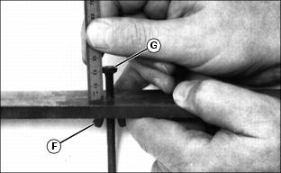
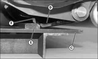
a. To adjust to less than 1.6 mm (1/16 in.) or check for parallelism, loosen wing nut (F) on gauge bar bolt. Set height of cut by measuring from the top of the gauge to the bottom of the head of the bolt (G). Lock wing nut (F).
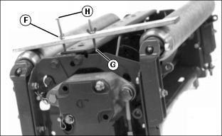
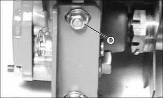
b. Hook head of bolt (G) over edge of bed knife. (Cutting unit is upside down for photo clarity.)
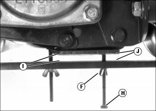
c. Loosen wing nut (F). Turn bolt (H) until gauge is parallel with bed knife. Measure distance between front (I) and rear (J) of the bottom of the bed knife to top of gauge. Distance should be the same at both points.
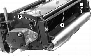
6. Adjust Rear Roller Assembly:
NOTE: Set rear roller first and then adjust front roller. Rear rollers come from factory set and leveled at 19 mm (3/4 in.) cut. To avoid binding mechanisms, make small adjustments on each end of the roller.
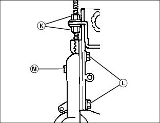
a. Loosen bolts (L) and adjustment nuts (K) (both sides) on the rear roller and center the bolts in the slots. Tighten bolts and adjustment nuts.
b. To adjust roller in 1.6 mm (1/16 in.) increments, loosen nut (M) (both sides) to allow positioning the roller as close to the gauge bar as possible without touching it. Tighten nuts (K). Ensure the same number of rachet teeth are exposed at each end of the roller.
c. To adjust height of cut to less than 1.6 mm (1/16 in.), loosen bolts (L) and turn adjustment nuts (K) alternately until roller just touches the gauge bar. This is determined by turning the roller and listening for the scratching sound from roller on gauge bar. Repeat on opposite end. Recheck the adjustment for the opposite side and readjust if necessary.
d. Tighten all hardware and recheck with gauge bar to ensure setting did not change.
7. Adjust Front Roller Assembly:
NOTE: Set rear roller first and then adjust front roller. To avoid binding mechanisms, make small adjustments on each end of the roller.
a. Loosen bolts (L) and adjustment nuts (K) (both sides) on the rear roller and center the bolts in the slots. Tighten bolts and adjustment nuts.
b. To adjust roller in 1.6 mm (1/16 in.) increments, loosen nut (M) (both sides) to allow positioning the roller as close to the gauge bar as possible without touching it. Tighten nuts (K). Ensure the same number of rachet teeth are exposed at each end of the roller (should match rear roller setting).
c. To adjust height-of-cut to less than 1.6 mm (1/16 in.), loosen bolts (L) and adjustment nuts (K) and turn adjustment nuts (K) alternately until roller just touches the gauge bar. This is determined by turning the roller and listening for the scratching sound from roller on gauge bar. Repeat on opposite end. Recheck the adjustment for the opposite side and readjust if necessary.
d. Tighten all hardware and recheck with gauge bar to ensure setting did not change.
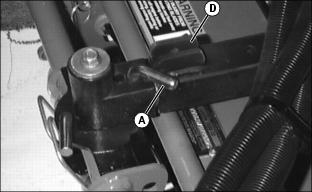
Height-of-Cut Field Adjustment (22 ESP)
IMPORTANT: Avoid damage! Never adjust rollers so that there is more than 1.6 mm (1/16 in.), or one notch, difference between front and back rollers or cutting geometry will be affected. |
NOTE: Use the following procedure to make quick routine changes in height-of-cut. For necessary adjustments after servicing the cutting units or to adjust HOC for less than 1.6 mm (1/16 in.), see Adjusting Height-of-Cut After Servicing in this section.
1. Lower cutting units and shut off engine. Lock park brake.
2. Loosen nut (A) on both sides of roller. Move roller adjusters (B) up or down for height selection. Adjusting one roller one notch adjusts the HOC 1.6 mm (1/16 in.). Adjusting front and rear rollers both one notch will change HOC 3.2 mm (1/8 in.).
Adjusting Reel-to-Bed Knife Clearance (22 ESP)
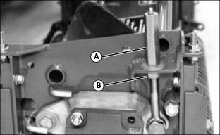
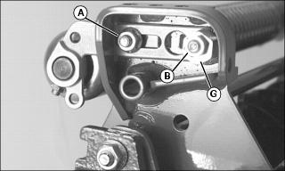
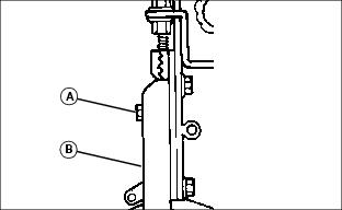
NOTE: Each flat on the adjustment nut represents 0.025 mm (0.001 in.) movement of the reel. The lower nut (B) will lower the reel when turned counterclockwise and the upper nut (A) will raise the reel when turned clockwise (as viewed from the top of the unit).
1. Adjust the ends of the reel to set clearance with a 0.05 mm (0.002 in.) feeler gauge.
2. Inspect the entire length of the bed knife with a 0.102 mm (0.004 in.) feeler gauge (C).
· It should not go in anywhere. If it does, go to step 4.
· If the reel is making contact anywhere, go to step 3.
NOTE: Always rotate the reel in the reverse direction to avoid damaging or dulling the cutting edges of the reel or the bed knife.
3. Slowly rotate the reel backwards, watching for contact between the reel and the bed knife at the center of the bed knife.
· If contact is made, grind the reel and bed knife to eliminate the "frown" in the bed knife or the out-of-round condition of the reel.
4. Measure the clearance at the center of the bed knife.
· If the clearance exceeds 0.102 mm (0.004 in.), grind the reel and bed knife to eliminate the "smile" in the bed knife or the out-of-round condition of the reel.
5. When adjusted and sharpened correctly, each reel blade should cut a single piece of newspaper held at 90° to the top surface of the bed knife along the entire length of the bed knife. Reel should not make contact with bed knife with 0-0.05 mm (0-0.002 in.) maximum clearance. If not, grind reel and bed knife as necessary.
Adjusting Grass Deflector (22 ESP)
NOTE: Front discharge of grass clippings will minimize grass clumps on fairway.
Front Discharge
· Position deflector (A) in down position.
NOTE: Install rod (C) in hole so bent end is opposite the cutting unit motor.
· Place rods (B) and (C) in holes and secure with spring pins.
Rear Discharge
2. Rotate deflector (A) to up position.
3. Install rod in upper hole (D) and secure with pull pin.
Maximum Rear Discharge Opening
· Remove both rods holding deflector and move the deflector (A) to raised position. Place rods through holes (E and F) and secure with pull pins.
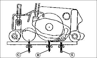
Emptying the Grass Catchers (22 ESP)
1. Stop machine on a level place and lock park brake.
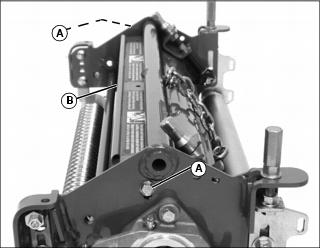
2. Move the mow-transport lever to transport to disengage reels, but leave units raised with the front wing units level.
4. Wait until all moving parts have stopped.
5. For rear cutting units, pull the bent pin (A) just enough to rotate the rear cutting units.
6. Release the catcher hook (B) and remove basket.
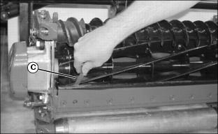
7. Place one hand on top of the basket and the other hand in the back (C) of the basket to remove basket.
8. Place the grass catcher basket back onto the yoke and turn the cutting unit forward to the mowing position. The pin (A) will fall back into place and lock the cutting unit in its forward facing position.
9. Release the catch hook to remove basket for the front three cutting units.
Operating (Optional) Fairway Tender Conditioner
IMPORTANT: Avoid damage! Help prevent dulling of blades. Do not use fairway tender conditioner (FTC) for three days following top dressing. |
The conditioner process involves shallow vertical cutting. The blades are adjusted to cut runners and lift horizontal leaf material. It is important that frequent and thorough observations be performed or stress to the plants may occur. Make adjustments as necessary.
NOTE: It is normal for grass catchers to fill faster when conditioning.
1. Condition fairways the first time with blades set the same as height-of-cut. Closely examine each fairway and note any inconsistencies or appearance of over-aggressiveness. Decrease FTC penetration if necessary.
2. Check each fairway 1-2 hours after cutting. Look for any tendency toward a yellow or brown tint. This indicates over-stress.
3. If visible stress is observed, decrease FTC penetration to 0.39 mm (0.016 in.).
4. Continue cutting/conditioning at this setting for three to five days. Check frequently for stress.
5. If no stress is observed, increase FTC penetration by 0.25 mm (0.010 in.). Check for obvious over-aggressiveness. Observe for two to three days, watching for signs of stress.
6. Repeat step 5, until stress becomes visible. Back off the FTC adjusted penetration by 0.25 mm (0.010 in.).
NOTE: Stress is a cumulative result of many factors such as irrigation, temperature, humidity, chemical application, disease, thatch, etc.
Conditioning aggressiveness will require adjustment and monitoring as these factors vary.
Conditioning frequency may also need to be reduced in some cases.
Adjusting (Optional) Fairway Tender Conditioner
NOTE: Height-of-cut must be adjusted prior to adjusting the fairway tender conditioner.
Adjustment is shown for a 2500M cutting unit. Adjustment for 22 ESP is the same.
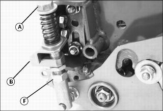
· Press down on FTC adjuster bolts (A).
· Swing adjuster stops (B) around toward the front of the cutting unit.
2. Position cutting unit for making height-of-cut adjustment.
3. Set FTC adjustment screw (C) on the gauge bar to the desired operating height.
· Adjustment screw (D) may need to be loosened so that the gauge bar can rest on both the front and rear rollers.
4. Place preset gauge bar on cutting unit. Hook height of cut screw (E) on bed knife. The ends should rest firmly on the front and rear rollers.
5. Loosen adjuster locknut (F) on both ends of the cutting unit.
6. Turn adjuster bolts (A) to raise or lower FTC roll. Alternate from end to end until the teeth touch the screw on the gauge bar. Tighten adjuster locknuts (F).
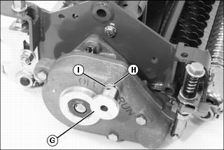
· Pull knob (G). Turn knob clockwise to the RUN position. Knob must engage detent (H).
· Turn knob counterclockwise to the OFF position. Knob must engage detent (I).
10. Disengage FTC adjuster stops.
· Press down on FTC adjuster bolts (A).
· Swing adjuster stops (B) around toward the rear of the cutting unit.
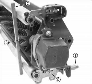
Adjusting (Optional) Rear Roller Power Brush
NOTE: Adjustment is shown for a 2500M cutting unit. Adjustment for 22 ESP is the same.
It is not necessary to remove the brush cover to adjust the powered brush.
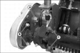
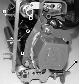
1. Loosen idler gear pivot locknut (A).
2. Loosen both pivot bracket locknuts (B), if equipped.
3. Loosen two bolts (C) on left side of cutting unit.
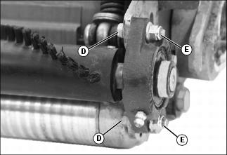
4. Loosen two bolts (D) and locknuts (E) on right side of cutting unit.
NOTE: The brush bristles should just barely clear the full length of the roller. The gap between the brush bristle tips and the roller should be approximately 1 mm (1/32 in.).
5. Slide the rear roller powered brush (F) up or down to adjust the roller.
6. Tighten bolts (C) on left side of cutting unit and bolts (D) and locknuts (E) on right side of cutting unit.
7. Tighten both pivot bracket locknuts (B) and the idler gear pivot locknut (A).
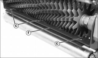
Operating and Adjusting (Optional) 2500M Vertical Cutters
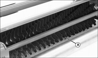
Picture Note: Vertical cutting units (A) are intended for thatch removal and should not be set for ground engagement. The cutters should not be set to penetrate the soil. For excess thatch conditions, several trips across the green may be necessary. Do not attempt to remove large amounts of thatch in a single cutting.
· Adjust mow speed limit to no more than 4.8 km/h
(3 m.p.h.). The mow speed should be set properly to ensure that the cutting reels do not stall out completely.
· Initial adjustment of blade depth should be flush with the bottom of the rollers. The depth can be increased as needed from this point to achieve desired results. Do not exceed a blade depth of 3 mm (0.12 in.).
· Before making a vertical cutter adjustment, measure the usable blade length of the cutting blades. If usable blade length is less than the desired cutting depth, replace blades before continuing.
Adjusting Cutting Depth
1. Mark the desired cutting depth (B) on a gauge bar (C).
2. Place the gauge bar across the front and rear rollers approximately 50 mm (2 in.) in from the end of the rollers.
3. Loosen locknut (D) on each side of the cutting unit.
4. Adjust position of rear roller.
· Turn each tower adjuster (E) until leading edge of vertical cutting blade aligns with the cutting depth mark on the gauge bar.
· Rotate cutting reel back and forth to ensure blade tip does not extend beyond the depth mark.
· Check both ends of cutting reel until they are adjusted to the same setting.
· If the vertical cutter cannot be adjusted because of wear, replace the blades and then adjust to the correct depth.
NOTE: Adjustment of rubber flap height will depend on turf conditions.
· On short turf, lower the flap to prevent material from flying out the rear of the cutting unit.
· On turf with a lot of thatch, raise the flap to allow the removed thatch to exit out the rear of the cutting unit.
6. Adjust cutting unit rubber flap (F).
· Loosen three carriage bolts (G) and hex nuts.
· Adjust the flap approximately 13 mm (1/2 in.) up from the bottom of the rollers.
7. Repeat procedure for other cutting units.
Operating and Adjusting Optional Vertical Cutters (22 ESP)
NOTE: Installation of optional scalping motors are recommended for use with the vertical cutters.
IMPORTANT: Avoid damage! Do not operate the cutting units in a "stalled" mode. This will cause excessive heating of the hydraulic oil. |
1. Adjust mow speed limit to no more than 4.8 km/h (3 mph). The mow speed should be set properly to ensure that the reels do not stall out completely.
2. Adjust blade depth flush with the bottom of the rollers.
· The depth can be increased as needed from this point to achieve desired results. Do not exceed a blade depth of 3.0 mm (0.12 in.).
IMPORTANT: Avoid damage! Adjust both ends of the roller evenly to avoid binding the adjustment mechanism. |
NOTE: Before making adjustment, measure the usable blade length of the cutting blades. If the usable blade length is less than the desired cutting depth, replace blades before continuing.
3. Adjust cutting depth. Mark the desired cutting depth (A) on a gauge bar.
4. Place the gauge bar across the front and rear rollers approximately 50 mm (2 in.) in from the end of the rollers.
5. Adjust the front roller height to bring the leading edge (B) of the cutting blade in line with the mark on the gauge bar. Rotate reel back and forth to ensure blade tip does not extend beyond depth mark.
6. Adjust pivot arms to raise or lower the cutting blades, if desired depth cannot be achieved with roller adjustment.
7. If vertical cutter cannot be adjusted because of wear, move rear adjuster bolts to top holes (C).
8. Adjust front adjuster bolts in slot (D) evenly on both ends of cutting unit as necessary.
9. For excess thatch conditions, several trips across the area to be thatched may be necessary. Do not attempt to remove large amounts of thatch in a single cutting.
Adjusting Rotary Cutting Units (IRS)
1. Stop machine on level surface.
2. Lower cutting units to ground.
3. Move the mow-transport lever to transport position, lock park brake and stop engine.
4. Remove ring from pin and remove pin from adjustment hole.
5. Insert pin into desired adjustment hole and retain with ring. Repeat for other 3 adjusters.
Adjusting Cutting Unit Down Pressure (Optional For 3225C)
Lightweight Fairway Mower theoretical down pressure reading versus down force exerted at the cutting unit.