Operating
Daily Operating Checklist
o Test safety interlock system.
o Inspect tires and check air pressure.
o Check for loose, missing, or damaged parts.
o Check engine oil level, and for leaks.
o Check transaxle oil level, and for leaks.
o Check hydraulic oil level (auxiliary reservoir), and for leaks.
o Check coolant level, and for leaks.
o Check and clean air intake screen and fan shroud.
o Check fuel tank level, and for leaks.
o Check area below machine for any leaks.
Avoid Damage to Plastic and Painted Surfaces
• Do not wipe plastic parts unless rinsed first.
• Insect repellent spray may damage plastic and painted surfaces. Do not spray insect repellent near machine.
• Be careful not to spill fuel on machine. Fuel may damage surface. Wipe up spilled fuel immediately.
Adjusting Seats
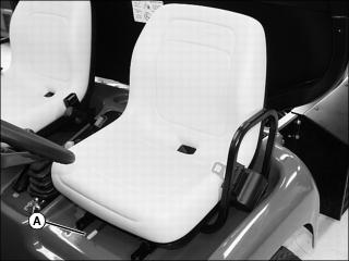
1. Sit on the operator or passenger seat.
2. Pull and hold lever (A) to the left.
3. Slide seat forward or rearward to desired position.
Using Seat Belts
To Connect the Seat Belt:
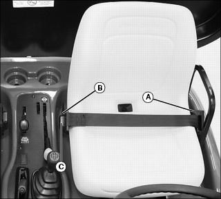
• With one continuous motion pull seat belt from retractor (A) and across hips and waist.
NOTE: If seat belt stops short of being able to insert into latch, allow belt to return into the retractor and pull again.
• Insert buckle into latch (B) on other side of seat. When properly inserted into the latch a click should be heard.
To Disconnect the Seat Belt:
• Press red button (C). Allow seat belt to return to retractor.
Testing Safety Systems
The safety systems installed on your machine should be checked before each machine use. Be sure you have read the machine operator manual and are completely familiar with the operation of the machine before performing these safety system checks.
Use the following checkout procedures to check for normal operation of machine.
If there is a malfunction during one of these procedures, do not operate machine. See your authorized dealer for service.
Perform these tests in a clear open area. Keep bystanders away.
Testing Seat and Park Brake Switches
3. Move gearshift lever to the neutral position.
5. With engine running at slow idle, raise off seat.
6. Engine must continue to run.
Result: Engine must stop within five seconds. If the engine does not stop, there is a problem with the safety interlock circuit. See your authorized dealer.
Testing Neutral Switch
3. Move the gearshift lever to the “R” (reverse) position.
4. Turn the key switch to the start position.
6. Repeat starting procedure with shift lever in each gear.
8. Move the gearshift lever to the neutral position.
9. Turn the key switch to the start position.
Result: Engine should crank. If the engine should start with the gearshift lever in any position other than the neutral position, there is a problem with the safety interlock circuit. See your authorized dealer.
Testing Auxiliary Hydraulic System Switch
NOTE: Make sure no attachments are connected to the auxiliary hydraulic quick-couplers at the rear of the vehicle.
3. Move the gearshift lever to the neutral position.
4. Pull up hydraulic PTO lever to the ON position.
5. Turn the key switch to the start position.
Result: Engine must not crank. If the engine should start, there is a problem with the safety interlock circuit. See your authorized dealer.
Using Light Switch
NOTE: Using headlights for extended periods of time without engine running will discharge the battery.
1. Push in on top of rocker switch to turn lights on.
2. Push in on bottom of rocker switch to turn lights off.
Using Fuel Shut-Off Valve (Diesel Models)
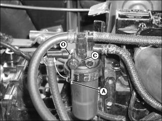
1. Locate fuel filter sediment bowl assembly on the right side of the engine.
Picture Note: Fuel shut-off valve shown in the open position.
2. Rotate two-position fuel shut-off valve lever (A) to the “O” (open) position or “C” (closed) position.
“C” (Closed) Position
• When performing any type of engine service.
• During periods of extended storage.
“O” (Open) Position
• Fuel shut-off valve must be in the full open position for proper fuel delivery to the engine.
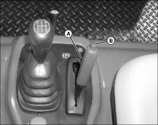
Using the Park Brake
To Lock Park Brake
• Pull up lever (A) and latch into position.
To Unlock Park Brake
• Push lever (A) down completely. Instrument panel indicator light must go out.
Using the Differential Lock Lever
The differential lock is used to provide better traction when the rear wheels of the vehicle start to slip. Engaging the differential lock lever will lock the left and right rear axles together and cause both rear wheels to turn at equal speeds for maximum traction.
IMPORTANT: Avoid damage! To prevent damage to differential, do not engage differential lock when either rear wheel is slipping. |
NOTE: Vehicle turning radius is increased when the differential lock is engaged.
To Engage Differential Lock:
• Pull up and hold differential lock lever in the raised position. Hold lever in the raised position as long as there is rear wheel slippage.
To Disengage Differential Lock:
• Lower differential lock lever.
Using Four Wheel Drive (4WD)
This is a manual shift 4WD system that allows the powertrain to drive the front wheels in addition to the rear wheels for improved traction on difficult ground conditions.
Engaging and Disengaging 4WD
• Push down on 4WD lever to engage.
• Pull up on 4WD lever to disengage. If traveling forward, it may be necessary to lift foot from the accelerator momentarily to allow 4WD to disengage.
Tips for operating 4WD:
• Maintain recommended front and rear tire pressures to ensure optimum performance on all surface conditions.
• Disengage 4WD when driving machine on paved or hard packed surfaces to increase front tire life and reduce drive train wear.
Using the Hydraulic PTO Control Lever
Perform this operational procedure with vehicles equipped with the auxiliary hydraulic kit. Engaging the hydraulic PTO lever will provide auxiliary hydraulics for attachments requiring the capability.
Dash indicator will illuminate when PTO is engaged.
To Engage the Hydraulic PTO:
• Pull up hydraulic PTO lever to the on position.
To Disengage the Hydraulic PTO:
• Push Hydraulic PTO lever down to the off position.
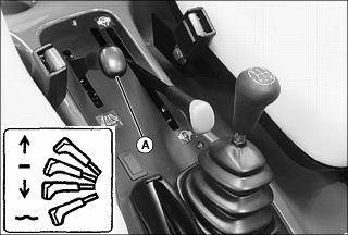
Using the Lift Cylinder Lever
To Raise Attachment
2. Pull and hold back lever (A) to raise attachment.
3. Release lever. Lever will return to the neutral position, and attachment will be held in position with the lift cylinder locked in place.
To Lower Attachment
NOTE: An attachment can be lowered and the lift cylinder will retract with the engine running or the engine stopped.
1. Push and hold down lever until attachment is lowered or positioned as desired.
2. Release lever. Lever will return to the neutral position, and attachment will be held in position, with the lift cylinder locked in place.
NOTE: When operating the machine with the auxiliary hydraulic PTO engaged, it is recommended that the lift cylinder lever be held down momentarily after the attachment has been lowered. This will firmly seat the load check for the lift cylinder spool which locks the lift cylinder in position.
When operating the machine with a cargo box attachment having the tailgate release kit installed, the lift cylinder lever must be held down momentarily after the box has been lowered. This will lock the tailgate and eliminate tailgate rattle.
To Allow Attachment to Float
NOTE: Float position allows the lift cylinder to move freely for use with some ground following attachments.
Placing the lift cylinder lever in the float position will cause a raised attachment to be lowered by gravity until completely down. For best control of raised loads, it is recommended that float position not be used to lower attachments.
1. Push lever (A) down, through “lower” position, and with additional force, push lever down past detent to lock lever into float position.
2. Pull up lever to release float position.
3. Release lever. Lever will return to the neutral position, and attachment will be held in position, with the lift cylinder locked in place.
Using the 4th and / or 5th Gear Lockout
NOTE: Setting the gear lockout requires access to the transmission shift input shaft located on the left side of the transmission, above the rear axle. If an attachment is installed, empty attachment, raise to service position, park safely (see Using the Lift Cylinder Safety Support in the Safety section) and install the safety support.
Make sure the vehicle is on a hard, level surface, the park brake is locked, the transmission is in “Neutral” and the key switch is turned to the STOP position prior to setting the fourth and/or fifth gear lockout.
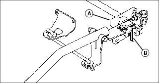
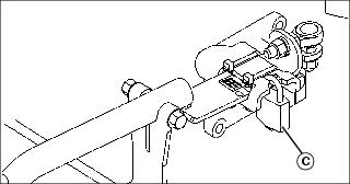
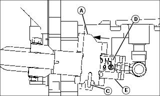
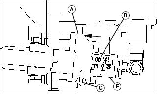
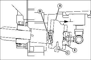
This vehicle is equipped with a lock channel feature (A) for 4th and/or 5th gear lockout. Preventing the use of 4th or 5th gear while limiting vehicle ground speed may be advisable in certain operating conditions.
The lockout feature was set at the factory (locked in position with a tie band) to allow the use of all gears. Use of the lockout feature requires removal of the factory tie band (B) and installation of a padlock (C) 4.8 mm (3/16 in.) diameter shackle.
NOTE: Padlock not supplied with the vehicle.
To Lock Out 5th Gear:
NOTE: Make sure the vehicle is on a hard, level surface, the park brake is locked, the transmission is in “Neutral” and the key switch is turned to the STOP position prior to setting the fourth and/or fifth gear lockout.
NOTE: Lock will not operate if vehicle transmission is already in 5th gear.
1. Move gearshift lever to any position except 5th gear.
2. Using padlock key, unlock padlock (C) and remove from lock channel (A).
3. Slide lock channel (A) forward, aligning slot with next hole in shift bracket (E).
NOTE: When lock channel is moved, label (D) indicates correct position for 5th gear lockout.
4. Install padlock (C) in lock channel (A) slot.
5. Remove safety support and lower attachment.
To Lock Out 4th and 5th Gear:
NOTE: Lock will not operate if vehicle transmission is already in 4th or 5th gear.
1. Move gearshift lever to any position except 4th or 5th gear.
2. Using padlock key, unlock padlock (C) and remove from lock channel (A).
3. Slide lock channel (A) forward, aligning slot with next hole in shift bracket (E).
NOTE: When lock channel is moved, label (D) indicates correct position for 4th and 5th gear lockout.
4. Install padlock (C) in lock channel (A) slot.
5. Remove safety support and lower attachment.
To Unlock 4th and/or 5th Gear:
NOTE: Setting the gear lockout requires access to the transmission shift input shaft located on the left side of the transmission, above the rear axle. If an attachment is installed, empty attachment, raise to service position, park safely (see Using the Lift Cylinder Safety Support in the Safety section) and install the safety support.
1. Using padlock key, unlock padlock (C) and remove from lock channel (A).
2. Slide lock channel (A) rearward, aligning slot with last hole in shift bracket (E).
NOTE: When lock channel is moved, label (D) indicates all gears available.
3. Install padlock (C) in lock channel (A) slot.
4. Remove safety support and lower attachment.
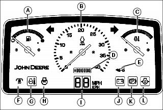
Instrument Panel
E - Four Wheel Drive (4WD) Indicator (If equipped)
G - Coolant Temperature Indicator
H - Glow Plug Circuit Indicator (Diesel Model)
J - Battery Low Voltage Indicator
L - Engine Oil Pressure Indicator
Tachometer (B) is an instrument used to determine speed. Engine speed is shown in 100s. Example: If indicator is pointing at 20 (20 x 100 = 2000 rpm).
Engine Coolant Temperature Gauge (C) will indicate if engine temperature becomes excessive. If the gauge indicator needle moves all the way into the red zone, stop vehicle engine immediately and determine cause.
Hour Meter (D) shows the approximate number of hours the engine has run. Use the hour meter and the Service Interval Chart to determine when the vehicle will need service.
Four Wheel Drive (4WD) Indicator (If equipped) (E) is visible only when lighted and will illuminate when the four wheel drive (4WD) is engaged.
PTO Indicator (F) is visible only when lighted and will illuminate when the hydraulic PTO lever is engaged.
Engine Coolant Temperature Indicator (G) will illuminate when the engine coolant approaches a dangerously hot temperature. Reduce engine to idle speed. Check the engine coolant level and make sure air flow to the radiator is not obstructed. Continued operation may cause higher temperatures resulting in damage.
Glow Plug Indicator (Diesel Model) (H) is visible only when lighted and will illuminate when the key switch is turned to the run position. The indicator light should go off approximately 3 seconds after the key switch is turned to the run position. This indicates that the engine glow plugs are on and preheating the engine combustion chamber.
Speedometer LED Display (I) will illuminate when the key switch is turned to the run position. This LED display indicates vehicle speed.
Battery Discharge Indicator (J) will illuminate when the key switch is turned to the run position. The indicator should turn off once the engine is started; if it continues to illuminate, the alternator may not be producing adequate current. Stop engine and determine cause.
Engine Oil Pressure Indicator (L) will illuminate when engine oil pressure is low. If lamp glows when engine is running, stop engine immediately. This is an indication that the engine may be low on oil, or major engine damage may have occurred.
Switching Engine Speedometer
1. Disconnect the battery negative cable.
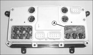
3. Locate mph/kph switch (A) on the back of instrument panel on your machine.
NOTE: The switches are set on machines using standard tires.
4. Toggle the switches from factory configuration for mph (B) to kph (C), using a screwdriver to reach each switch.
6. Connect the negative battery cable.
Operating the 5-Speed Synchronized Transmission
Using the Clutch Pedal
The functions of the clutch pedal are:
• Connects and disconnects engine power to the transmission.
• Operates in conjunction with the gearshift lever to shift gears.
To Disengage the Clutch:
• Press the clutch pedal down completely. This will disengage the transmission from engine power.
To Engage the Clutch:
• Remove foot from clutch pedal slowly. This will engage the transmission to engine power.
Using the Gearshift Lever
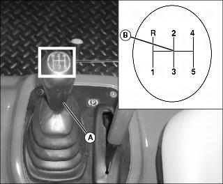
The gearshift lever (A) is located on a console to the right of the operator seat. The gearshift lever provides five forward travel speeds and one reverse speed.
Select a gear on the gearshift lever that matches desired speed and direction. First and second gears are very low and should be used when hauling heavy loads.
Forward Travel
NOTE: The gearshift lever must be in the neutral position for the engine to start.
2. Move the gearshift lever to the neutral position (B) between gears “2” and “3”.
3. Depress clutch pedal and start engine.
4. Move gearshift lever to a desirable starting gear.
• Vehicles with a load - first gear
• Vehicles with no load - second or third gear
6. Release clutch gradually to take up load smoothly.
• Depress clutch and shift to next gear.
Reverse Travel
3. Move gearshift lever to reverse.
Starting the Engine
NOTE: Diesel Models: Make sure fuel shut-off valve is open.
2. Push hydraulic PTO lever to the off position.
3. Move the gearshift lever to the neutral position.
4. Gas Models with Manual Choke: Pull the choke knob out to aid in starting the engine when cold. As engine warms up, push choke knob in until fully open. When starting a hot engine, choke knob should be pushed in.
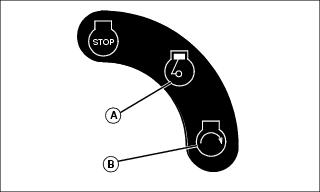
5. Turn key switch to the run position (A).
• Battery discharge indicator light should be on.
• Park brake indicator light should be on.
• Engine oil pressure indicator light should be on.
• Diesel Models: Glow plug indicator light should be on. After approximately three seconds indicator light will go off. Engine is now ready to start.
IMPORTANT: Avoid damage! Starter may be damaged if operated for more than 20 seconds at a time. Wait at least two minutes before trying again if engine does not start. |
7. Turn key switch to the start position (B).
NOTE: Engine is calibrated at the factory to slow idle at 1250 rpm
8. When engine starts, release key switch to the run position.
• Battery discharge indicator light should go out.
• Engine oil pressure indicator light should go out.
• Park brake indicator light should go out.
Stopping the Engine
1. Release accelerator pedal and allow engine to slow idle.
2. Depress the clutch pedal and the foot brake.
NOTE: Gasoline engine has a time delay between turning key switch to the stop position and when engine stops. Make sure engine has stopped before leaving vehicle.
3. Turn key switch to the stop position.
4. Place gearshift lever in first or reverse gear.
Operating Vehicle Engine with Operator Off the Seat
• Lock park brake at all times before leaving seat. • Do not leave seat with vehicle running unless attachment function requires it. |
NOTE: During normal operating conditions, the vehicle engine should stop running when the operator raises off the seat.
To keep engine running when operator is off the seat:
1. Depress clutch and foot brake pedals to stop the vehicle.
2. Move the gearshift lever to the neutral position.
4. Slowly release clutch and foot brake pedals.
• Engine should continue to run with the operator off the seat.
Towing the Utility Vehicle
1. Move gearshift lever to the neutral position.
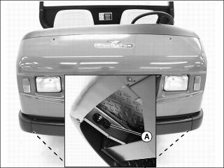
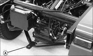
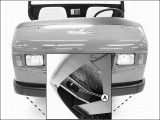
2. Attach a tow line to oval slot (A) provided on either side of the main frame under the front of the vehicle.
4. Tow vehicle slowly and carefully to desired location.
Towing Loads
• To provide adequate braking ability and traction, weight of towed load (trailer plus cargo) must never exceed the vehicle payload (operator plus passenger plus cargo box load).
• Do not tow a load that exceeds the maximum allowable towing load for this vehicle, as specified in this operator’s manual.
• Do not tow a load with this vehicle that exceeds 680 kg (1500 lb).
• Do not exceed a tongue weight of 90.7 kg (200 lb).
• Tow load at a speed slow enough to maintain control.
• Always use rear hitch point (A) provided on and approved for this utility vehicle. This is an approved hitch point; do not modify in any way.
Transporting Utility Vehicle
1. Drive vehicle forward onto a trailer.
2. Park vehicle safely. (See Parking Safely in the Safety section.)
4. Block rear wheels with chocks or wood blocks.
5. Fasten vehicle to trailer with heavy-duty straps, chains, or cables.
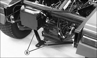
• The tie downs should be attached to oval slots (A) provided on both sides of the main frame under the front of the vehicle and both sides of the hitch assembly (B) at the rear of the vehicle.
• Both front and rear straps must be directed down and outward from the vehicle.
6. When transporting the utility vehicle on a road or highway, use accessory lights and devices for adequate warning to operators of other vehicles. Check local, state, provincial, or federal laws.
Raising and Lowering the Cargo Box
2. Pull and hold back lift cylinder lever to raise cargo box.
NOTE: The lift cylinder will retract and the cargo box will lower with the engine running or the engine stopped.
Pushing the lever down beyond the lower position into the detented float position will cause the box to drop more slowly then in the lower position, as the circuit is restricted to avoid a sudden drop.
3. Push and hold down lever to lower cargo box.
Operating the Cargo Box Tailgate
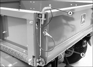
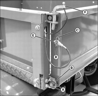
1. Pull up and remove each tailgate latch pin (A).
IMPORTANT: Avoid damage! The tailgate fully lowered can contact the rear fenders and cause structural damage. Do not operate utility vehicle with the tailgate fully lowered. |
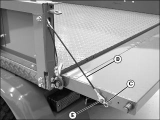
3. Remove spring locking pin (C) and cable (D) from each drilled stud (E) to fully lower tailgate.
Removing the Cargo Box Tailgate
1. Close the tailgate and latch both sides.
2. Remove two screws (A) and tailgate support plates (B) from each side.
3. Remove spring locking pin (C) and cable (D) from each drilled stud (E).
