
Operating - Cutting Units
Cleaning Cutting Unit
• When cleaning do not direct high pressure water at the reel motor seals. Water may be drawn into bearings as they cool.
• Use high volume, low-pressure water to clean exterior of machine, the foot platform area and the reels.
• Do not use water to wash where electrical components are located. If water penetrates electrical connections it may create problems.
• Use compressed air not water to clean air screens. Reduce compressed air to less than 210 kPa (30 psi) when using for cleaning purposes. Clean grease fittings before lubricating. Replace lost or broken fittings immediately.
Adjusting Bed Knife-To-Reel
NOTE: Reel must be free to turn by hand.
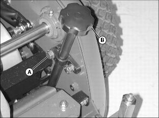
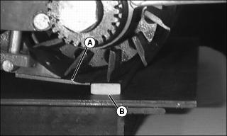
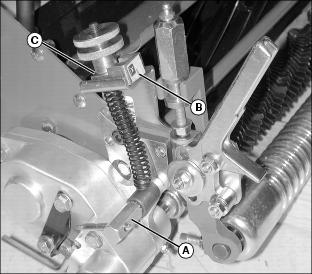
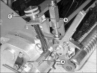
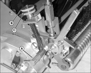
1. To adjust clearance between knife and reel blades, loosen clamp nut (A).
2. Turn adjusting knob (B) clockwise to decrease clearance.
• Turn adjusting knob (B) counterclockwise to increase clearance.
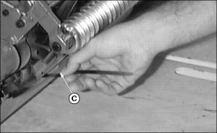
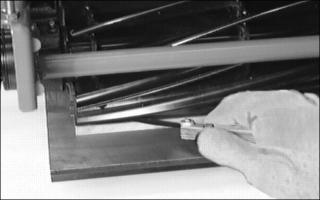
3. Adjust ends of reel to 0.001” with feeler gauge (C).
4. Now inspect the entire length of the bed knife with a 0.002” feeler gauge. It should not go in anywhere if it does, go to step 7.
5. If the reel is contacting anywhere, go to Step 6.
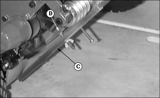
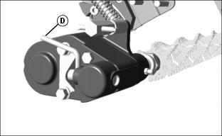
NOTE: Always rotate the reel in the reverse direction to avoid damaging or dulling the cutting edges of the reel or bed knife.
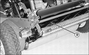
6. Slowly rotate the reel (D) backwards watching for contact between the reel and bed knife at the center of the bed knife. If contact is made, backlap the reel and bed knife to eliminate the “Frown” in the bed knife or the out-of-round condition of the reel.
7. Measure the clearance at the center of the bed knife. If the clearance exceeds 0.002 of an inch, backlap the reel and bed knife to eliminate the “Smile” in the bed knife or the out-of-round condition of the reel.
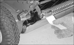
8. When properly adjusted and sharpened, each reel blade should cut a piece of paper held at 90 degrees to the top surface of the bed knife along the entire length of the bed knife with 0.000 -0.001” clearance.
NOTE: Do not overtighten knife to reel. Overtightening
can cause damage to knife or cutting edges.
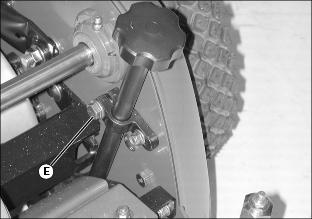
9. Tighten clamp nut (E) on both sides.
Adjusting Cutting Height
NOTE: Always adjust bed knife to reel before adjusting cut height.
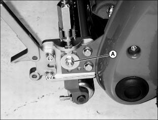
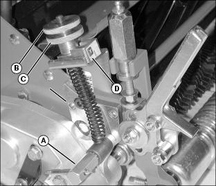
1. Loosen nut (A) on each side until adjusting bracket slides easily.
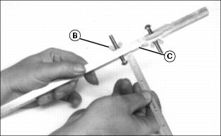
2. Loosen wing nut (B) and set gauge (C) to desired cutting height.
3. Place gauge (C) against bottom of front and rear rollers and bed knife cutting surface.
4. Move front roller up or down using adjusting knob.
5. Adjust height to gauge (C) by adjusting front roller until knife becomes slightly tight to underside of screw head (D).
7. Check cutting height on both ends with gauge. Readjust height as necessary.
8. Tighten lock nuts on both sides.
Adjusting Drive Roller Parallel with Bed Knife
NOTE: Adjust bed knife-to-reel before adjusting roller for parallelism.
1. Park machine on a level surface.
2. Move RUN/OFF switch to OFF position.
3. Move travel clutch lever to NEUTRAL position.
7. Place the machine on a flat bench plate so that the bed knife (A) contacts the rear edge of the support bar (B).
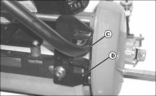
8. Support handlebars (C) so that they are centered in each support bracket (D). DO NOT lift the traction roller off bench plate.
9. Check gap at each end of reel. If gap is 0.1 mm (0.004 in.) or less, no adjustment is necessary. If adjustment is required, proceed to next step.
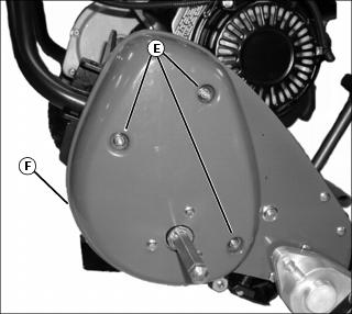
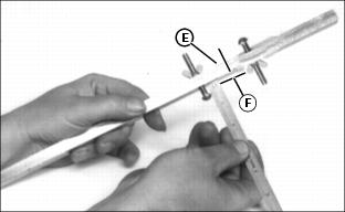
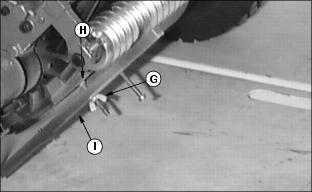
10. Remove flange nuts (E) and remove right drive cover (F).
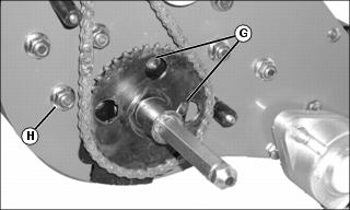
11. Rotate roller until holes in sprocket align with bearing holder cap screws (G). Loosen two cap screws.
12. Loosen nut (H) attached to eccentric screw.
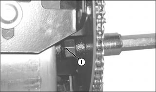
13. Position eccentric dot (I) at position as shown. Rotate eccentric until gap at ends of reel is less than 0.1 mm (0.004 in.).
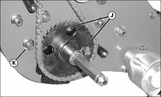
14. Tighten eccentric screw and nut (K) and bearing holder cap screws (J) to 22 N•m (16 lb-ft).
16. Install transport wheels and drive collars (if equipped).
Operating Greens Tender Conditioner (GTC)
Or Rotary Brush
NOTE: Stress is a cumulative result of many factors such as irrigation, temperature, humidity, chemical application, disease, thatch, etc.
Conditioning aggressiveness will require adjustment and monitoring as these factors vary.
Conditioning frequency may also need to be reduced in some cases.
The conditioner process involves shallow vertical cutting. The blades are adjusted to cut runners and lift horizontal leaf material. It is important that frequent and thorough observations be performed or stress to the plants may occur. Make adjustments as necessary.
Condition greens the first time with blades set the same as HOC. Closely examine each green and note any inconsistencies or appearance of over-aggressiveness. Decrease GTC penetration if necessary.
Check each green 1 - 2 hours after cutting. Look for tendency toward a yellow or brown tint. This indicates over-stress.
If visible stress is observed, decrease GTC penetration. Check frequently for stress.
Engaging the GTC
1. Loosen T-handles (A) on each side.
2. Move slide block (B) so that adjusting knob (C) is setting on lower step.
4. Tighten T-handles (A) on each side.
5. Turn handle (D) up to the detent run position.
Disengaging the GTC
1. Turn handle (D) down to the detent off position.
2. Loosen T-handles (A) on each side.
3. Move slide block (B) so that adjusting knob (C) is setting on the top step.
5. Tighten T-handles (A) on each side.
Adjusting Greens Tender Conditioner (GTC)
Or Rotary Brush
3. Set adjusting knob (C) on lower step of sliding block (D).
5. Measure from underside of screw head to top of gauge (E). This is the cutting height (F).
6. Loosen wing nut (G) and adjust screw (H) to 1mm (1/32-in.) above the cutting height (with rotary brush), or a maximum of 1mm (1/32-in.) below the cutting height (with greens tender conditioner).
7. Place gauge (I) against bottom of front and rear rollers and bed knife cutting surface.
8. Use adjusting knob (C) to set height on each side.
11. Repeat for the other side.
NOTE: If brush or cutter is not adjusted correctly, lower engine rpm or the machine pulling to one side can be expected.