
Operating
Daily Operating Checklist
o Make sure all necessary guards and shields are safely and securely attached. Check for loose, missing, or damaged parts.
o Remove mower deck belt shields. Clean grass and debris from belt area.
o Remove grass and debris from machine and mower deck.
o Remove grass and debris from operator’s platform, air intake screen, engine cooling fins, transmissions, engine compartment, and muffler area.
o Check engine and transmission oil levels.
o Check all belts for damage or cracking.
o Adjust cutting height if necessary.
o Check wheel bolt torque. Tighten if necessary.
o Check tire air pressure. Check tires for damage or cracking.
o Check and adjust steering control linkages.
Avoid Damage to Plastic and Painted Surfaces
• Do not wipe plastic parts unless rinsed first. Using a dry cloth may cause scratches.
• Insect repellent spray may damage plastic and painted surfaces. Do not spray insect repellent near machine.
• Be careful not to spill fuel on machine. Fuel may damage surface. Wipe up spilled fuel immediately.
• Prolonged exposure to sunlight will damage hood surfaces.
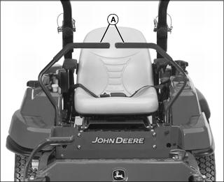
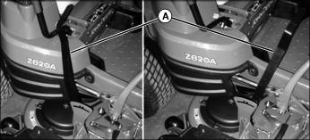
Raising and Lowering Operator Seat
Raising the Seat
1. Park machine safely. (See Parking Safely in the SAFETY section.)

2. Stand on side of the machine and lift seat.
3. Slide seat rod (A) through the frame cutout (B).
4. Set the seat rod in the cutout of the frame.
Lowering the Seat
1. Stand on the side of the machine.
2. Reset seat rod into the slide of the frame cutout.
3. Lower seat and return vehicle into service.
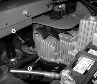
Mounting and Dismounting Machine Safely

When mounting and dismounting the machine, do so from the left side of the machine using the step (A) or the foot plate (B). Park machine safely (see Parking Safely in the SAFETY section) before dismounting. Do not mount or dismount the machine from the front.
Adjusting Seat
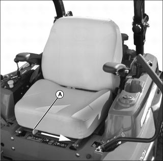
2. Push and hold the seat adjustment lever (A) toward the middle of the seat.
3. Slide forward or backward to desired position.
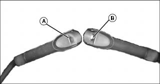
Using Seat Belt
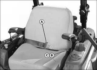
2. Pull out seat belt buckle (A) and stretch across your lap in one nonstop motion.
3. Insert seat belt buckle into latch (B) until it locks.
4. To release seat belt, press red button (C) until buckle comes out of latch.
Raising and Lowering ROPS
1. Park machine safely. (See Parking Safely in the SAFETY section.)
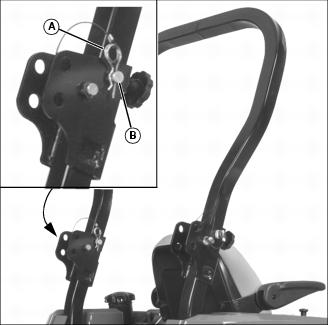
2. Remove spring pin (A) from drilled pin (B) on left and right sides of ROPS.
3. Remove drilled pin from left and right sides of ROPS.
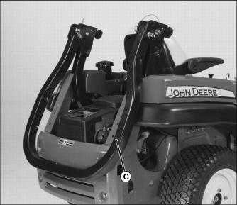
4. Pull ROPS rearward to lowered position (C).
5. Install drilled pins and spring pins back into holes in ROPS to secure in place.
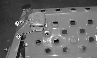
Using Anti-Rattle Knob
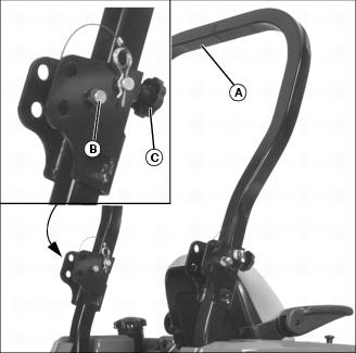
1. With the spring pins and drilled pins installed, push the upper ROPS (A) rearward so it’s securely against positioning pin (B).
2. Tighten anti-rattle knob (C).
3. Repeat for other side of ROPS.
Placing ROPS into Intermediate Position
NOTE: When a Material Collection System attachment is installed, the ROPS cannot be fully lowered. If the ROPS must be lowered, place it into the intermediate position.

1. With the spring pins and drilled pins installed, push the upper ROPS (A) rearward so it is securely against positioning pin (B).
2. Tighten anti-rattle knob (C).
3. Repeat for other side of ROPS.
Determining Safe Slope Angles
1. Lay a straight piece of sturdy lumber 1.2 m (4 ft) long on the slope.
2. Measure the angle of the slope with an angle indicator or protractor level.
• If slope is greater than 20°, do not mow.
• If slope is 10° or less the risk for rollover is low.
3. Repeat procedure at several points on the slope to get an overall idea of the slope angle. Do not operate the machine on any areas that exceed the manufacturer’s recommended slope angle.
Using Convenience Package Controls (If Equipped)
Electric Deck Lift
1. Park machine safely. (See Parking Safely in the SAFETY section.)
2. Push button (A) on left motion control lever to raise mower deck.
PTO Shut Off
NOTE: Once PTO has been shut off using the button the PTO switch must be pushed down and pulled up again to engage PTO.
• Push button (B) on right motion control lever to shut off PTO.
Setting Mower Deck Cutting Height
Cutting height can be adjusted from approximately 38 to 127 mm (1-1/2 to 5 in.). Each increment on the knob adjusts the height-of-cut (HOC) approximately 6 mm (1/4 in.).
The deck can also be raised and locked in a transport position, to provide maximum ground clearance when moving the machine from one area to another.
Adjusting
1. Park machine safely. (See Parking Safely in the SAFETY section.)
3. Stop engine and lock park brake.
NOTE: If machine is equipped with convenience package raise and lower deck with power lift switch located on left control lever.
4. Raise mower deck using deck lift pedal.
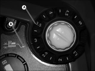
5. With deck in raised position, adjust height of cut knob (A) to align cut height to index mark (B).
6. Release pedal to lower deck to desired setting.
Transport Lock
The deck can be locked in a transport position to give maximum ground clearance when the machine is moved to and from various work sites.
The Transport Lock function allows the deck to be returned to the previous Height of Cut after being in the transport position.
1. Park machine safely. (See Parking Safely in the SAFETY section.)
3. Stop engine and lock park brake.
NOTE: If machine is equipped with convenience package raise and lower deck with power lift switch located on left control lever.
4. Raise mower deck using deck lift pedal.
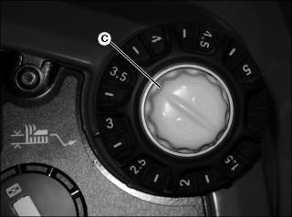
5. With deck in raised position, rotate knob (C) counter clockwise into the transport lock position.
6. Release pedal to lower deck to transport setting.
Release Transport Lock
NOTE: If machine is equipped with convenience package raise and lower deck with lift switch located on left control lever.
1. Raise mower deck using deck lift pedal.
2. Rotate transport lock knob clockwise. Knob will release to off position.
3. Release pedal to lower deck to previous height of cut setting.
Adjusting Mower Deck - All Models
NOTE: Mower deck anti-scalp wheels should not contact the ground while adjusting deck.
1. Park machine safely. (See Parking Safely in the SAFETY section.)
2. Inflate tires to the correct pressure.
3. Raise the mower deck to the transport position.
Checking Level (Side-to-Side)
NOTE: Mower deck anti-scalp wheels should not contact the ground.
1. Lower deck to the 76 mm (3 in.) cutting height position.
2. Position right mower blade (discharge side) in the straight forward (front-to-rear) position.
NOTE: Use a short ruler or a leveling gauge (Part No. AM130907) (A) to check the mower blade level.
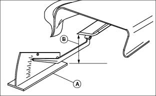
Picture Note: Discharge chute raised for photo clarity.
3. Measure distance (B) from the right front blade tip to the ground.
• The front blade tip should be 3 in. (+/- 1/16 in.) from the ground.
4. Position left mower blade in the straight forward (front-to-rear) position.
5. Measure distance (B) from left front blade tip to the ground.
• The front blade tip should be 76 mm (3 in.) (+/- 2 mm [1/16 in.]) from the ground.
6. If the blade tip height is not within the given tolerance then further adjustment is necessary.
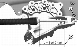
Adjusting Blade Tip Height
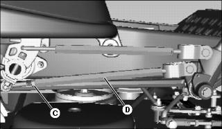
2. Turn rod tube (D) on each side of machine to adjust as needed so the left and right blade tips are at 3 in. (+/- 1/16 in.).
NOTE: If an adjustment was made to the front blade tip height, the blade rake will need to be checked.
Checking Blade Rake (Front to Rear Height)
1. Lower mower deck to 76 mm (3 in.) cutting height position.
2. Position right mower blade (discharge side) in straight forward (front-to-rear) position.
3. Measure from the right front blade tip to the ground.
4. Turn blade one hundred eighty degrees and measure from right rear blade tip to the ground.
NOTE: Use a short ruler or a leveling gauge (Part No. AM130907) (A) to check the mower blade level.
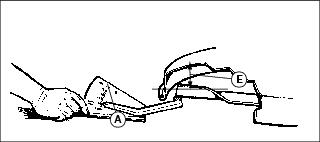
5. The height (E) of the rear blade tip should be between 3-6 mm (1/8-1/4 in.) higher than the front blade tip.
6. Repeat steps 1-5 for left blade
7. If the blade rake is not within the given tolerance then further adjustment is necessary.
Adjusting Blade Rake (Front-to-Rear)
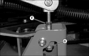
1. Loosen rear hanger jam nut (F).
2. Turn tube nut (G) at rear hangers to adjust front-to-rear level.
3. The rear of the blade tips should be 1/8-1/4 in. higher than front.
4. Tighten jam nuts to 67 N•m (50 ft-lb).
5. Check blade rake. Repeat adjustment if needed.
Adjusting Deck Lift Spring Tension
NOTE: Deck lift spring tension is adjusted at the factory. If the effort required to raise or lower the mower deck is not satisfactory, an adjustment may be necessary.
Check Spring Tension
1. Park machine on a hard, level surface.
2. Stop engine and lock park brake.
3. Raise the mower deck to the transport position.
NOTE: Both deck lift spring assemblies must be adjusted equally.
Do not over-tension the deck lift springs. If the springs are compressed too tightly, the mower deck will float too freely.
Decrease deck lift spring tension if operating in rough terrain.
Adjust Spring Tension
NOTE: Do not over tension the deck lift springs. If the springs are compressed too tightly, the mower deck will float too freely.
Decrease deck lift spring tension if operating in rough terrain.
While looking from rear of machine:
• Turn hex nut (B) clockwise to increase deck lift spring tension.
• Turn hex nut (B) counterclockwise to decrease deck lift spring tension.
Adjusting Mower Deck Anti-Scalp Wheels
NOTE: The flattest cut can be achieved by having all anti-scalp wheels adjusted off the ground. Check anti-scalp wheel adjustments each time the mower deck cutting height is changed.
It is recommended that all anti-scalp wheels be kept off the ground to minimize scuffing.
1. Inflate tire to correct pressure.
2. Adjust mower deck to desired cutting height.

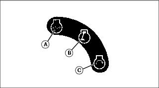
3. Adjust anti-scalp wheel (A) to one of three positions (B).
• Remove cap screw (C) and nut (D).
• Adjust wheel up or down so it is approximately 6-13 mm (1/4-1/2 in.) above mowing surface.
4. Install wheel with attaching hardware.
5. Adjust all wheels to the same height.
Testing Safety Systems

The safety systems installed on your machine should be checked before each machine use. Be sure you have read the machine operator manual and are completely familiar with the operation of the machine before performing these safety system checks.
Use the following checkout procedures to check for normal operation of machine.
If there is a malfunction during one of these procedures, do not operate machine. See your authorized dealer for service.
Perform these tests in a clear open area. Keep bystanders away.
Testing PTO Switch
3. Pull PTO knob up to engage.
4. Turn key switch to the start position.
Testing Park Brake Switch
2. Push PTO knob down to disengage.
4. Turn key switch to the start position.
Testing Seat Switch
3. Pull PTO knob up to engage.
4. Raise slightly off the seat.
Testing the Park Brake

1. Stop machine on a 17° slope (30% grade). Stop the engine and lock the park brake.
Using the Park Brake
Always lock the park brake and remove the key before leaving the machine unattended. |
Locking Park Brake
• Depress park brake lever (A) to lock park brake.
Unlocking Park Brake:
• Depress park brake release (B) to unlock park brake.
Using Key Switch
Picture Note: Key switch label.
A - STOP Position - With key in STOP position, all switched power is off, and engine should not run.
B - Run Position - Turn key from STOP to this position and all switched power circuits will be on.
C - Start Position - Turn key to start position to crank the engine. Release key after engine has started and it will automatically return to the run position. The engine will continue to run.
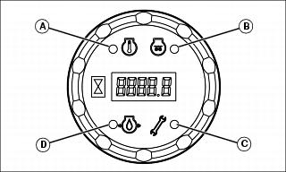
Using Indicator Lights
Using the PTO
Engage PTO:
1. Move throttle lever to the 1/2 to 3/4 fast position.
2. Pull PTO knob up to engage mower deck.
3. Move throttle lever forward to the fast position for mowing.
Disengage PTO:
Using the Throttle Lever
• Push throttle lever all the way forward to the fast position when mowing.
• Move throttle lever to the half throttle position when starting and warming the engine.
• Pull throttle lever to rear to slow position to idle engine. Do not run engine at slow idle any longer than necessary.
Using the Hour Meter
• The hour meter shows number of hours the machine has run.
• The service interval chart gives necessary service intervals. Use the hour meter and service interval chart to determine when machine will need service.
Using the Motion Control Levers
The functions of the motion control levers are:
• Dual function neutral position.
Neutral Lock Position

• Forward and reverse movement of the motion control levers (A) is prevented when levers are moved to the neutral lock position.
• Operator can exit mower with the engine running when the PTO switch is disengaged, the motion control levers are in the neutral lock position and the park brake is locked.
• Motion control levers must be in the neutral lock position to safely enter and exit the operator seat.
Neutral Position
• Machine speed, motion, and direction can be controlled when the engine is running, motion control levers are in the neutral position (A), and the park brake is unlocked.
Forward and Reverse Motion:
1. Move throttle lever to the fast position.
3. Move both motion control levers from the neutral lock position inward to the neutral position.
4. Push the control levers forward to begin forward motion.
• The farther forward the control levers are moved, the faster the machine will travel.
5. Pull both control levers rearward at the same time to begin reverse motion.
6. To stop motion, move both motion control levers forward or rearward until the machine comes to a stop.
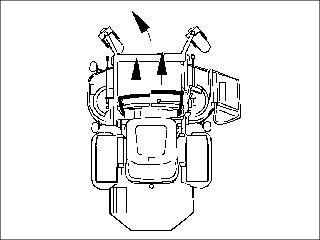
Forward:

• Push both motion control levers forward at the same time.
Reverse:

• Pull both control levers past center rearward at the same time.
Gentle Left Turn:
• Push right control lever further forward than the left control lever.
Gentle Right Turn:

• Push left control lever further forward than the right control lever.
Sharp Left Turn:
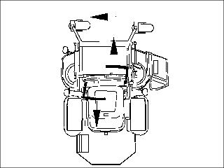
• Push right control lever forward and pull left control lever rearward at the same time.
Sharp Right Turn:
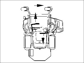
• Push left control lever forward and pull right control lever rearward at the same time.
Starting the Engine
3. Push the PTO knob down to disengage the PTO.
4. Move throttle lever to set engine speed:
NOTE: The starter will shutdown after 20 seconds of cranking. The key can be cycled from OFF to start and the starter will begin cranking again. After three cycles of cranking for 20 seconds (60 total seconds) the controller activates a thermal shutdown until components cool down.
6. Turn key switch to the start position.
• Turn key to start position again for no more than 20 seconds.
• Repeat the procedure if necessary.
IMPORTANT: Avoid damage! Unnecessary engine idling may cause engine damage. Excessive idling can cause engine overheating, carbon build-up, and poor performance. |
7. Release key to the run position when the engine starts.
• Push choke knob down to the off position.
• Move throttle lever to the fast idle position.
Engaging Mower
1. Adjust mower deck to desired cutting height.
3. Move throttle lever to the 1/2–3/4 throttle position.
5. Move both motion control levers to the neutral position.
NOTE: In cold weather or with a new machine, it may be necessary to engage the choke at the same time as the PTO knob to prevent the engine from stalling.
6. Pull PTO knob up to engage mower deck.
7. Move throttle lever to the fast position.
NOTE: The travel speed and turn rate will vary with the amount that the control levers are moved.
8. Push motion control levers forward slowly. Mow at a safe travel speed.
9. To stop machine motion, move both motion control levers in the opposite direction of motion until machine comes to a stop.
Operating Mulch-On-Demand Mower Deck (MOD) If Equipped
1. Park machine safely. (See Parking Safely in the SAFETY section.)
2. Place motion control levers in neutral lock position.
3. Push deck mode lever (A) forward until lever locks into the mulch position.
4. Pull deck mode lever towards operator until lever stops in side discharge mode.
Stopping Engine
IMPORTANT: Avoid damage! To help prevent engine backfiring, throttle lever should be set at the 1/2 throttle position and run for 30 seconds prior to stopping the engine. |
1. Move the motion control levers to the neutral lock position.
3. Move throttle lever to the 1/2 throttle position.
4. Turn key switch to STOP position.
Always lock the park brake and remove the key before leaving the machine unattended. |
Using the Bypass Pump Release Valves
IMPORTANT: Avoid damage! Transmission damage may occur if the machine is towed or moved incorrectly: |
NOTE: Both bypass pump release valves must be fully turned clockwise (closed) during normal vehicle operation.
When the machine needs to be moved without starting the engine, use the bypass pump release valves:
2. On both transmissions turn bypass valve (A and B) one and one half to two full turns counterclockwise to the open position.
4. Push machine to desired location. Due to hydraulic system drag, machine will move slowly.
6. Turn both bypass pump release valves one and one half to two full turns clockwise to the closed position. Tighten the valve to 19 N•m (14 lb-ft).
Transporting Machine on Trailer
NOTE: Trailer capacity must exceed combined machine weight and attachment weight. (See Specifications section in operator’s manual).
Be sure trailer has all the necessary lights and signs required by law.
1. Park trailer on level surface.
2. Raise mower deck before driving machine onto trailer.
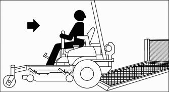
3. Back machine onto heavy-duty trailer with full-width ramp.
4. Lower mower deck completely.
6. Turn off machine and remove key.
7. Fasten machine at the axle or frame to trailer with heavy-duty straps, chains, or cables. Both front and rear straps must be directed down and outward from machine.
Mowing Tips
• Mow grass with throttle lever in the full fast / mow position.
• Keep mower deck and discharge chute clean.
• Properly level mower deck for a smooth cut.
• Use a travel speed that fits the conditions:
• Mow tall or wet grass twice. Cut grass at half desired height – then cut at desired height.
• Travel slow when mowing tall or thick grass.
• Avoid damaging grass by slipping or skidding machine drive wheels. Practice smooth control lever movements.
• When performing sharp turns, do not allow inside machine drive wheel to stop and twist on grass.
Mowing Travel Speeds
• Normal mowing on level ground.
Dismounting to Inspect Mower
1. Park machine on a hard, level surface.
2. Push knob down to disengage PTO.
3. Move motion control levers to the neutral lock position.
5. Stop engine and remove key. Wait for mower blades to stop turning before leaving operator’s seat.