
Service Engine
Engine Warranty Maintenance Statement
Maintenance, repair, or replacement of the emission control devices and systems on this engine, which are being done at the customer’s expense, may be performed by any non-road engine repair establishment or individual. Warranty repairs must be performed by an authorized John Deere dealer.
Avoid Fumes
Engine Oil
Use oil viscosity based on the expected air temperature range during the period between oil changes.
The following John Deere oils are preferred:
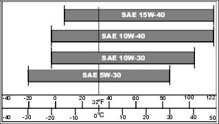
• TURF-GARD® (For gasoline engines)
• PLUS-4® (For gasoline and diesel engines)
• PLUS-50® (For diesel engines)
• TORQ-GARD SUPREME® (For diesel engines)
These oils meet the industry specification API Service Classification JS, CF, or higher.
Raising and Lowering Engine Hood
1. Park the vehicle safely. (See Park Safely in the SAFETY section.)
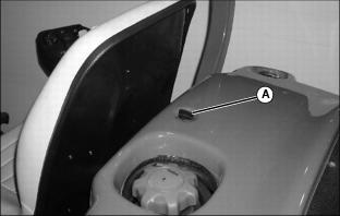
2. Turn button (A) counterclockwise to unlock hood.
4. Lower rear engine hood to close.
5. Turn button clockwise to lock hood in the lowered position.
Raising and Lowering Operator Seat
Raising the Seat
1. Adjust operator seat rearward as far as possible.
2. Raise and tilt operator seat forward.
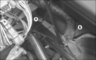
3. Remove prop rod (A) secured in stored position under operator seat platform.
4. Install prop rod (A) in channel slot (B).
Lowering the Seat
2. Remove prop rod from channel slot.
3. Secure prop rod in stored position under operator seat platform.
Checking Engine Oil
1. Park the vehicle safely. (See Park Safely in the SAFETY section.)
IMPORTANT: Avoid damage! Dirt and contamination can enter engine when checking oil level. Clean area around dipstick before loosening or removing. |
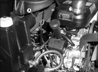
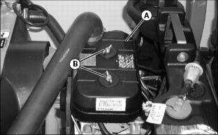
Picture Note: Gas Engine Shown
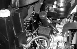
3. Remove dipstick (A). Wipe with a clean cloth.
6. Check oil level on dipstick; oil level should be between levels (B) and (C) on the dipstick.
7. If oil is low, add oil to bring oil level no higher than level (B) on the dipstick.
8. If oil level is above level (B) on the dipstick, drain to proper level.
Changing Engine Oil and Filter (Gas)
1. Run engine to warm the oil.
2. Park the vehicle safely. (See Park Safely in the SAFETY section.)
4. Place container under oil drain location.
NOTE: Attaching a section of plastic or rubber hose to the end of drain valve will help prevent engine oil from draining onto the center lift arm.
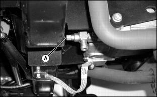
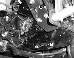
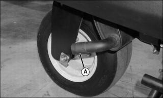
5. Open drain valve (A) to drain oil.
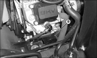
6. Wipe dirt from around oil filter (B) located under right side of engine.
7. Turn filter counterclockwise to remove.
• 2500E Hybrid filter is best removed with a strap-wrench.
8. Put a light coat of clean engine oil on the gasket of new filter.
9. Install replacement oil filter by turning to the right (clockwise) until rubber gasket contacts filter base. Tighten filter an additional one-half turn.
10. Close oil drain valve (A). DO NOT overtighten.
12. Add approximately 1.8 L (1.9 qt) of engine oil.
14. Start and run engine at idle to check for leaks. Stop engine. Fix any leaks before operating.
15. Check engine oil level. Add oil if necessary.
Changing Engine Oil and Filter (Diesel)
1. Run engine to warm the oil.
2. Park the vehicle safely. (See Park Safely in the SAFETY section.)
4. Place container under oil drain location located under left side of engine.
6. Wipe dirt from around oil filter (B) located under left side of engine.
7. Turn filter counterclockwise to remove.
8. Put a light coat of clean engine oil on the gasket of new filter.
9. Install replacement oil filter by turning to the right (clockwise) until rubber gasket contacts filter base. Tighten filter an additional one-half turn.
10. Install oil drain plug (A). DO NOT overtighten.
12. Add approximately 2.2 L (2.3 qt) of engine oil.
14. Start and run engine at idle to check for leaks. Stop engine. Fix any leaks before operating.
15. Check engine oil level. Add oil if necessary.
Cleaning Oil Cooler Coils and Radiator Cooling Fins (2500B)
• Clear work area of bystanders. • Wear eye protection when using compressed air for cleaning purposes. |
IMPORTANT: Avoid damage! Reduced air intake can cause overheating. Keep hydraulic oil cooler coils and radiator cooling fins clean. |
1. Park the vehicle safely. (See Park Safely in the SAFETY section.)
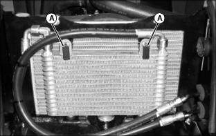
4. Move oil cooler away from radiator (if equipped).
• Release latches (A) securing oil cooler to the radiator mounting bracket.
• Carefully move oil cooler away from the radiator.
IMPORTANT: Avoid damage! Engine components may be damaged when cleaning oil cooler coils and radiator fins. Take care to prevent water and debris from entering the air intake hose. |
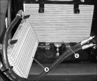
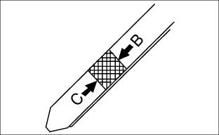
5. Remove dirt and debris from oil cooler coils (B) and radiator fins (C) using compressed air or water.
6. Check oil cooler coils and radiator fins for damage.
7. Install oil cooler (if equipped).
Checking Spark Arrestor
2. Loosen built-up carbon with a screwdriver or pick.
3. Clear debris from spark arrestor using compressed air.
Servicing Air Cleaner Element (Gas)
IMPORTANT: Avoid damage! Dirt and debris can enter the engine when the filter element is removed. Do not run engine without both air cleaner elements installed. |
1. Park the vehicle safely. (See Park Safely in the SAFETY section.)
4. Clean any dirt or debris surrounding air cleaner assembly before removing cover.
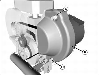
5. Remove air cleaner cover (A) by loosening both wing nut bolts (B).
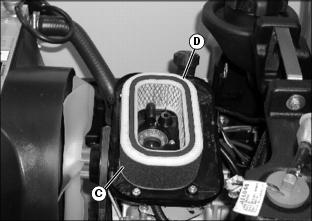
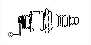
7. Inspect foam precleaner (C) and inside of paper element (D) for dirt and debris without removing it.
8. If foam precleaner is dirty, carefully remove paper filter and precleaner away from the air cleaner housing.
9. Carefully lower air cleaner cover over carburetor opening to keep dirt out of carburetor.
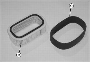
10. Remove foam precleaner (C) from paper element (D).
NOTE: DO NOT wash paper element.
11. Wash precleaner in a solution of warm water and liquid detergent.
12. Rinse precleaner thoroughly. Squeeze out excess water into a dry cloth until precleaner is completely dry.
14. Replace paper element with a new element only if damaged or very dirty.
15. Install foam precleaner onto new paper element.
16. Carefully raise air cleaner cover. Install air cleaner element into air cleaner housing.
17. Install air cleaner cover with wing nut bolts.
Checking Air Restriction Indicator (Diesel)
1. Park the vehicle safely. (See Park Safely in the SAFETY section.)
NOTE: Indicator will not function correctly if plastic indicator housing is damaged.
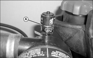
3. Check air restriction indicator. When red plunger inside indicator shows in clear window (A), air cleaner requires immediate service
Servicing Air Cleaner Element (Diesel)
Servicing Primary Air Filter Element
1. Park the vehicle safely. (See Park Safely in the SAFETY section.)
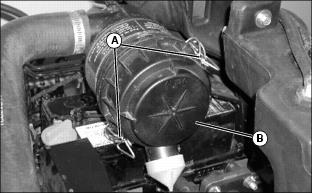
4. Release latches (A) and remove air cleaner canister cover (B).
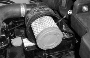
5. Remove and discard primary element (C). Replace with a new primary filter element.
6. Install air cleaner canister cover with rubber dust unloading valve pointing downward.
7. Check instruction molded into canister cover for proper installation.
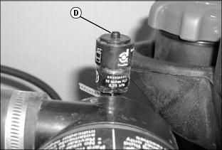
9. Push reset button (D) on air restriction indicator.
10. Start engine. Allow engine to run approximately one minute at maximum throttle speed.
12. Check air restriction indicator. If yellow plunger inside air restriction indicator is visible inside the red zone, replace secondary air filter element.
Servicing Secondary Air Filter Element
1. Remove air cleaner canister cover.
2. Remove primary air filter element.
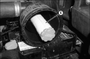
3. Remove and discard secondary air filter element (E). Replace with a new secondary air filter element.
4. Install primary air filter element.
5. Replace air cleaner canister cover.
6. Push reset button on air restriction indicator.
Cleaning Dust Unloading Valve
IMPORTANT: Avoid damage! Do not operate engine without air cleaner element and rubber dust unloading valve installed. |
1. Park the vehicle safely. (See Parking Safely in the SAFETY section.)
3. Access the engine compartment.
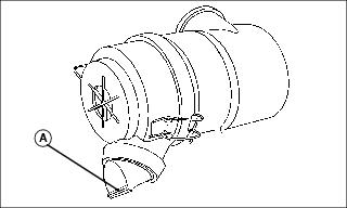
4. Squeeze dust unloading valve (A) to clean. Remove and replace if damaged.
Checking Spark Plugs (Gas)
1. Park the vehicle safely. (See Park Safely in the SAFETY section.)
3. Disconnect battery negative (-) terminal.
5. 2500E Hybrid Model: Move 48V alternator to access the right spark plug.
a. Remove alternator belt from 48V alternator.
b. Loosen lower hex head bolts (A).
c. Remove hex head bolt (B) and swing alternator away from engine.
6. Clean area around both spark plugs.
7. Disconnect spark plug wire (C) from each plug.
• Pitted or damaged electrodes.
10. Clean spark plugs carefully with a wire brush.
NOTE: Replace spark plugs with resistor plugs only.
11. Replace spark plugs as necessary.
12. Check and adjust spark plug gap (D).
• Gap must be 0.7 mm (0.028 in.).
13. Install and tighten spark plugs. Tighten plugs to 25 N•m (18 lb-ft.).
14. Install both spark plug wires.
15. 2500E Hybrid Model: Install 48V alternator.
a. Swing alternator toward cylinder head and install hex head bolt (B).
b. Tighten hex head bolts to 88 N•m (65 lb-ft).
c. Install alternator belt and guard.
17. Connect battery negative (-) cable.
Replacing Fuel Filter (Gas)
1. Park the vehicle safely. (See Park Safely in the SAFETY section.)
4. Locate fuel filter on right side of engine.
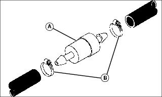
5. Slide hose clamps (B) away from fuel filter (A).
6. Place a drain pan under hoses to catch any fuel that may be left in the hoses.
7. Disconnect hoses from filter.
NOTE: Make sure fuel filter is installed with arrow pointing in direction of fuel flow toward engine.
9. Connect hoses to new filter.
11. Close rear engine cowling.
Adjusting Carburetor
NOTE: Carburetor is calibrated by the engine manufacturer and is not adjustable.
If engine is operated at altitudes above 1829 m (6,000 ft), some carburetors may require a special high altitude main jet. See your authorized dealer.
If engine is hard to start or runs rough, check the TROUBLESHOOTING section of this manual.
Possible engine surging will occur at high throttle with transmission in N neutral and mower engagement lever disengaged. This is a normal condition due to the emission control system.
After performing the checks in the troubleshooting section and your engine is still not performing correctly, contact your authorized dealer.
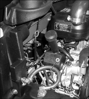
Servicing Sediment Bowl (Diesel)
1. Park the vehicle safely. (See Park Safely in the SAFETY section.)
Checking
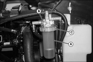
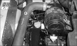
Picture Note: Fuel Shut-off Valve Shown in Open Position
1. Check for water in sediment bowl (A):
• Orange ring will float on top of the water.
2. If necessary, clean bowl and replace filter.
Cleaning
1. Close fuel shut-off valve (B).
2. Turn collar (C) to remove bowl and filter. Discard filter.
4. Install new filter and bowl.
5. Tighten collar and open fuel shut-off valve.
Bleeding Diesel Fuel System
1. Park machine on a level surface.
2. Place mow-transport lever in the transport position.
3. Lower attachments to the ground.
5. Be sure fuel is in fuel tank. Add fuel if necessary.
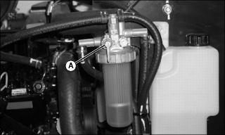
6. Open fuel shutoff valve (A).
7. Turn key to RUN position for two minutes prior to starting engine. The fuel pump will pressurize the fuel and remove any air in the system.
8. Start engine. If engine will not start, repeat previous step.
Checking and Adjusting Fan Belt (2500B Gas)
Checking Belt Tension
1. Park the vehicle safely. (See Park Safely in the SAFETY section.)
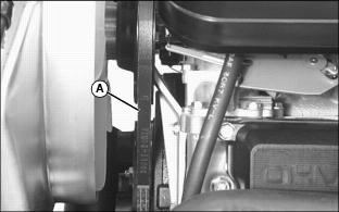
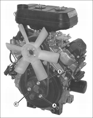
4. Inspect fan belt (A) for excessive wear, damage or stretching while in position on the fan and flywheel sheaves.
5. Apply thumb pressure to the belt approximately halfway between the sheaves. Belt should deflect inward approximately 9.5 mm (3/8 in.).
Adjusting Belt Tension
NOTE: Removal of engine spark plugs will allow for easier rotation of sheave assembly when performing this service procedure.
1. Remove both engine spark plugs.
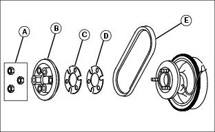
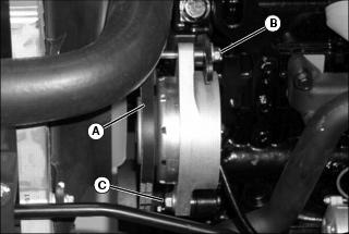
2. Remove three hex nuts (A) attaching outer half of sheave (B) to the engine flywheel.
3. Remove fan belt (E) if replacement is necessary.
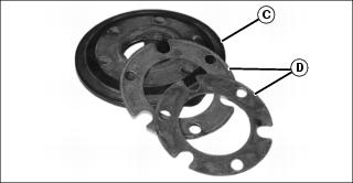
NOTE: Add shims between the sheave halves to lessen belt tension, and remove shims to increase belt tension. The minimum recommended number of shims allowed is one 0.6-mm-thick shim (C) and the maximum is two 0.6-mm-thick shims and one 1.2-mm-thick shim (D). Unused shims can be installed outside of outer sheave half.
All shims must be used when a new belt is installed.
4. Remove spacer shim(s) to increase belt tension.
5. Loosely install belt between sheave halves while installing outer half of sheave onto three threaded flywheel studs.
6. Rotate sheave assembly as nuts are tightened to allow belt to center in sheave halves and not be pinched in an off-center position.
7. Tighten nuts to 20-30 N•m (15-21 lb-ft).
8. Apply thumb pressure to the belt approximately halfway between the sheaves. Belt should deflect inward approximately 9.5 mm (3/8 in.).
Checking and Adjusting Alternator Belt (2500E Hybrid Gas)
1. Inspect belt for excessive wear or fraying.
2. Inspect the grooved side of belt for cracking or abnormal wear. Replace as necessary.
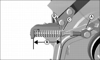
3. Inspect ball joint (A) for loosness or abnormal wear.
• Measure tension at a point midway between engine pulley and 48 V alternator pulley. Tension should be approximately 50 N (11 lbf) when belt is deflected 30 mm (1-3/16 in.).
• Spring length (B) should fall within notch (D). The spring measurement should be 66-72 mm (2-3/5-2-4/5 in.)
5. If tension adjustment is needed, loosen or tighten nut (C) as required.
Checking and Adjusting Alternator Belt (2500E Hybrid Diesel)
1. Inspect belt for excessive wear or fraying.
2. Inspect the grooved side of belt for cracking or abnormal wear. Replace as necessary.
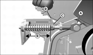
3. Inspect ball joint (A) for loosness or abnormal wear.
• Measure tension at a point midway between engine pulley and 48 V alternator pulley. Tension should be approximately 50 N (11 lbf) when belt is deflected 30 mm (1-3/16 in.).
• Spring length (B) should fall within notch (D). The spring measurement should be 66-72 mm (2-3/5-2-4/5 in.)
5. If tension adjustment is needed, loosen or tighten nut (C) as required.
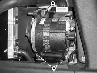
Checking and Adjusting Alternator Belt (2500B Diesel)
Checking Belt Tension
1. Park the vehicle safely. (See Park Safely in the SAFETY section.)
3. Inspect alternator belt (A) for excessive wear, damage or stretching while in position on the fan, alternator and flywheel sheaves.
4. Apply thumb pressure to the belt approximately halfway between the sheaves. Belt should deflect inward approximately 9.5 mm (3/8 in.).
Adjusting Belt Tension
1. Loosen adjustment bolt (B).
2. Loosen alternator mounting bolt (C).
3. Apply outward pressure to the alternator housing.
4. Tighten alternator adjustment bolt and mounting bolt.
5. Apply thumb pressure to the belt approximately halfway between the sheaves. Belt should deflect inward approximately 9.5 mm (3/8 in.).
Replacing Fan Belt (2500B Gas)
Removing
NOTE: Disconnect and remove spark plugs to allow for easy flywheel rotation during outer sheave half installation.
2. Remove three (3) nuts (A) from bottom pulley.
3. Remove outer half of bottom pulley (C) and shims (D) from flywheel.
4. Work belt (B) between tips of fan and fan shroud to remove belt.
Installing
1. Work belt between tips of fan blades and fan shroud, and place belt in fan pulley.
2. Install shims, belt, and outer half of bottom pulley.
NOTE: Slightly rocking fan while tightening pulley nuts will help to prevent belt from being pinched between pulley halves.
4. Install spark plugs and tighten to 25 N•m (221 lb-in.).
5. Run engine for a few seconds. Stop engine and check tension. Adjust if required. See Checking and Adjusting Fan Belt (2500B Gas) in this section.
Replacing Alternator Belt (2500E Hybrid Gas)
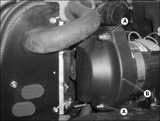
Removing
1. Remove key from key switch to prevent engine from being started.
2. Remove nut (A), washer, grommet and hex head bolt.
3. Remove nut (C), washer, grommet and hex head bolt.
5. Insert the square drive of a 3/8 in. breaker bar in the square hole (D) of the tensioner arm.
6. Pull on breaker bar to rotate belt tensioner and hold in that position.
7. While holding breaker bar, remove belt from alternator pulley first, then the remaining pulleys. Allow tensioner to rotate to a relaxed position.
8. Work belt between tips of fan and fan shroud to remove belt.
9. Inspect belt for wear, cracking, or other damage. Replace as necessary.
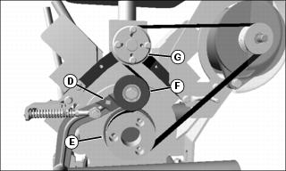
Installing
1. Work belt between tips of fan and fan shroud to install.
IMPORTANT: Avoid damage! Ensure belt is correctly seated in grooves of pulleys. Failure to do so will result in belt damage immediately after engine is started. |
2. Route belt around engine pulley (E), idler pulley (F), and fan pulley (G) as shown.
3. Use a breaker bar to rotate tensioner and hold in place.
4. Install belt over alternator pulley.
5. Install belt guard (B). Install hex head bolt, grommet, washer and nut (A) and tighten securely.
6. Install hex head bolt, grommet, washer and nut (C) and tighten securely.
7. Run engine for a few seconds. Stop engine and check tension. Adjust if required. See Checking and Adjusting Alternator Belt (2500E Hybrid Gas) in this section.
Replacing Alternator Belt (2500E Hybrid Diesel)
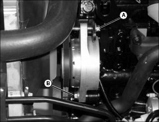
Removing
1. Remove key from key switch to prevent engine from starting.
4. Insert the square drive of a 3/8 in. breaker bar in the square hole (D) of the tensioner arm.
5. Pull on breaker bar to rotate belt tensioner and hold in that position.
6. While holding breaker bar, remove belt from 48 V alternator pulley (E) first, then the remaining pulleys. Allow tensioner to rotate to a relaxed position.
7. Work belt between tips of fan and fan shroud to remove belt.
8. Inspect belt for wear, cracking, or other damage. Replace as necessary.
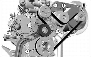
Installing
1. Work belt between tips of fan and fan shroud to install.
IMPORTANT: Avoid damage! Ensure belt is correctly seated in grooves of pulleys. Failure to do so will result in belt damage immediately after engine is started. |
2. Route belt around engine pulley (F), idler pulley (G), fan pulley (H), and 12 V alternator pulley (I) as shown.
3. Use a breaker bar to rotate tensioner and hold in place.
4. Install belt over 48 V alternator pulley.
5. Install belt guard (B). Install hex head bolt, grommet, washer and nut (A) and tighten securely.
6. Install hex head bolt, grommet, washer and nut (C) and tighten securely.
7. Run engine for a few seconds. Stop engine and check tension. Adjust if required. See Checking and Adjusting Alternator Belt (2500E Hybrid Diesel) in this section.
Replacing Alternator Belt (2500B Diesel)
1. Park the vehicle safely. (See Park Safely in the SAFETY section.)
4. Loosen alternator adjustment bolt (A).
5. Loosen alternator mounting hex head bolt (B).
6. Apply inward pressure to the alternator housing to loosen belt.
7. Remove worn belt from alternator, fan and flywheel sheaves.
9. Apply outward pressure to the alternator housing to put tension on belt.
10. Tighten alternator adjustment bolt (A) and mounting hex head bolt (B).
11. Apply thumb pressure to the belt approximately halfway between the sheaves. Belt should deflect inward approximately 9.5 mm (3/8 in.).
Service Cooling System Safely
Recommended Engine Coolant
The following John Deere coolants are preferred:
• COOL-GARD® PRE-DILUTED SUMMER COOLANT (TY16036).
• COOL-GARD® CONCENTRATED SUMMER COOLANT (TY16034).
If neither of the recommended coolants is available, use a glycol base coolant that meets the following specification:
Check container label before using to be sure it has the appropriate specifications for your machine. Use coolant with conditioner or add conditioner to coolant before using.
If using concentrate, mix approximately 50 percent antifreeze with 50 percent distilled or deionized water before adding to cooling system. This mixture will provide freeze protection to -37 degrees C (-34 degrees F).
Certain geographical areas may require lower temperature protection. See the label on your antifreeze container or consult your John Deere dealer to obtain the latest information and recommendations. Never exceed the maximum dilution rate for the coolant you are using. Exceeding the maximum rate will greatly reduce the coolant effectiveness.
Checking Coolant Level
1. Park machine safely. (See Parking Safely in the SAFETY section.)
2. Allow engine and radiator to cool.
4. Check coolant level in recovery tank.
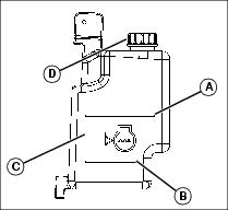
• If engine is warm, coolant should be between lines (A) and (B) on coolant recovery tank (C).
• If engine is cold, coolant level should be at line (B).
5. If necessary, remove recovery tank cap and add coolant to achieve proper level. Install and tighten recovery tank cap.
6. With engine cool, slowly open radiator cap to first stop to release all built up pressure.
7. Remove radiator cap and check coolant level inside radiator.
• Coolant level should be at base of the neck in fill port.
• If necessary, add coolant until radiator completely gull.
8. Install and tighten radiator cap.
9. clean debris from air intake screen and radiator.
10. Check condition of hoses. Check for leaks or loose connections.
11. Check condition of overflow hose between radiator and recovery tank. Verify hose is installed to bottom of recovery tank. Hose must not be kinked.
Draining Cooling System
1. Park machine safely. (See Parking Safely in the SAFETY section.)
3. With engine and cooling system cool, open radiator cap to the first stop to release all pressure. Press down on cap slightly and turn counterclockwise to remove.
4. Open radiator petcock. Drain coolant into a suitable container.
5. After all coolant has drained, close radiator petcock.
Flushing Cooling System
1. Park machine safely. (See Parking Safely in the SAFETY section.)
3. Drain cooling system and fill with clean water and John Deere Cooling System Cleaner, John Deere Cooling System Quick Flush, or an equivalent. Follow directions on the container.
4. Install and tighten radiator cap.
5. Start and run engine until it reaches operating temperature. Stop engine.
6. Open radiator petcock and drain the cooling system immediately before rust and dirt settle.
8. Fill cooling system with clean water and repeat flushing until system is clean.
9. Drain and fill cooling system.
Filling Cooling System
1. Park machine safely. (See Parking Safely in the SAFETY section.)
2. Allow engine and radiator to cool.
4. With engine and cooling system cool, open radiator cap to the first stop to release all pressure. Press down on cap slightly and turn counterclockwise to remove.
5. Fill cooling system. For cold weather, use a solution of only ethylene glycol antifreeze (without a stop-leak additive) and clean, soft distilled water. A chart on the antifreeze container tells how much antifreeze to use for the freeze protection needed in your area.
• Certain geographical locations may require lower temperature protection. See the label on your antifreeze container or consult your John Deere dealer to obtain the latest information and recommendations.
• John Deere Cooling System Sealer or its equivalent may be added to the radiator to seal leaks. DO NOT use any other additives in the cooling system.
NOTE: Cooling system capacity is 4.0L (4.2 qt).
6. add coolant to recovery tank until level reacges high line.
7. Start engine and watch coolant level in radiator. Add coolant as necessary to bring level up to filler neck.
8. Install and tighten radiator cap.
9. Run engine until it reaches operating temperature.
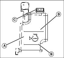
11. After the engine cools, check coolant level in recovery tank (A). ).
• If engine is warm, coolant level should be above line (B) but below line (D
• If engine is cold, coolant level should be at line (B).
12. I If necessary, remove cap (C) to add coolant to achieve proper level.
13. With engine cool, slowly open radiator cap to first stop to release all built up pressure.
14. Remove radiator cap and check coolant level inside radiator.
• coolant level should be at base of neck in fill port.
• If necessary, add coolant until radiator completely full.
15. Install and tighten radiator cap.
16. Check condition of coolant system hoses. Install new hoses periodically. Tighten hose clamps regularly.
Checking Radiator Hoses, Air Intake Hose and Hose Clamps
1. Park the vehicle safely. (See Park Safely in the SAFETY section.)