
Operating
Engaging Cutting Units
1. Pull raise-lower lever rearward to raise cutting units.
NOTE: If the cutting units are lowered to the ground before the mow-transport lever is moved to the mow position, the cutting reels will not rotate. Raise the cutting units before continuing with procedure.
2. Move mow-transport lever forward to the mow position.
NOTE: In noise-restricted areas, the engine can be slowed down to lower the noise and still maintain the proper reel speed. Ground speed will be reduced. Adjust ground speed as necessary.
RPM needs to be determined by mowing conditions.
Do not reduce throttle more than 50% (2000-2300 rpm). If low voltage indication occurs, increase throttle position.
3. Move throttle lever forward to fast position.
4. Slowly begin forward travel.
NOTE: The center cutting unit will raise and lower to the ground after the front cutting units.
The front cutting units will lower to the ground before the center cutting unit.
Moving the mow-transport lever to the mow position activates a switch so the cutting units automatically engage when lowered.
5. Push raise-lower lever forward to lower cutting units and start cutting reel rotation.
6. Pull back raise-lower lever to raise cutting units to transport lift height and automatically stop reel rotation.
Emergency Stopping - Cutting Reels
NOTE: There are two methods of stopping reel rotation in case of an emergency.
• Depress the park brake pedal and cutting reel rotation will stop.
• Move the Mow/Transport lever to the TRANSPORT position and cutting reel rotation will stop.
To begin cutting reel rotation:
• If the park brake was depressed, raise and lower cutting units.
• If the Mow/Transport lever was moved to TRANSPORT, move the Mow/Transport lever to the Mow position. Then raise and lower the cutting units.
Adjusting Cutting Unit Shield (QA5)
NOTE: Keeping the shield close to the cutting blades improves the performance of the grass catcher in most conditions.

1. Loosen two bolts (A) and locknuts on each side of cutting unit.
2. Raise or lower shield (B) to desired position.

• Maintain an approximate 1.5 mm (0.06 in.) clearance (C) between the bottom of the shield and the top of the cutting blades.
Removing and Emptying Grasscatchers
NOTE: Remove center grasscatcher from left side of machine.
Removing

1. Push in on link handle release bracket (A), and raise and remove link handle from catcher bracket support (B).
2. Pivot grasscatcher upward (C) from frame assembly and empty.
Installing
1. Pivot grasscatcher upward, push in on link handle release bracket, and hook link handle onto the catcher bracket support.
Operating Greens and Turf Conditioner
The conditioner process involves shallow vertical cutting. The blades are adjusted to cut runners and lift horizontal leaf material. It is important that frequent and thorough observations be performed or stress to the plants may occur. Make adjustments as necessary.
NOTE: The initial setting should be the same as Height Of Cut to prevent damage to the turf.
For a deeper cut, set approximately 0.79 mm (.032 in.) below Height Of Cut.
1. Set the GTC blades the same height as the Height of Cut when conditioning greens for the first time.
2. While cutting with GTC, closely examine each green for any inconsistencies or appearance of over-aggressiveness. Decrease GTC penetration if necessary.
3. Check each green 1–2 hours after cutting. Look for any tendency toward a yellow or brown tint. This indicates over-stress.
4. If visible stress is observed, decrease GTC penetration to 0.39 mm (0.016 in.) for next cutting.
5. Continue cutting/conditioning at this setting for three to five days. Check frequently for stress.
6. If no stress is observed, increase GTC penetration by 0.25 mm (0.010 in.). Check for obvious over-aggressiveness. Observe for two to three days, watching for signs of stress.
7. Mow with GTC at this setting until stress becomes visible. Back off the GTC adjusted penetration by 0.25 mm (0.010 in.).
NOTE: Stress is a cumulative result of many factors such as irrigation, temperature, humidity, chemical application, disease and thatch.
Conditioning aggressiveness will require adjustment and monitoring as these factors vary.
Conditioning frequency may also need to be reduced in some cases.
Operating and Adjusting (Optional) Vertical Cutters
IMPORTANT: Avoid damage! The vertical cutters produce excessive dust and fine grass particles. Check the air cleaning system frequently to prevent engine overheating. |
NOTE: Vertical cutting units are intended for thatch removal and should not be set for ground engagement. The cutters should not be set to penetrate the soil.
For excess thatch conditions, several trips across the green may be necessary. DO NOT attempt to remove large amounts of thatch in a single cutting.
Preparing Machine for Vertical Cutting
IMPORTANT: Avoid damage! Using the backlap valve to rotate the vertical cutting units in a reverse direction will cause serious damage to the hydraulic motors. |
NOTE: Less stress is put on hydraulic motors (2500B models) and the electric drive system (2500E Hybrid models) if reels are run in reverse direction.
2500B Models

1. Disconnect bulkhead to left cutting unit motor hose (A) from bulkhead location (B).
2. Disconnect right cutting unit motor to bulkhead hose (C) from bulkhead location (D).
3. Switch locations of hose ends (A) and (C).
• Connect hose end (A) to bulkhead at location (D).
• Connect hose end (C) to bulkhead at location (B).
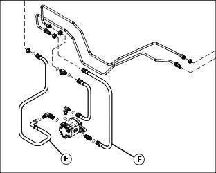
4. Swap hose ends (E) and (F) on the rear cutting unit motor.
2500E Hybrid Models

1. Open service access panel (E) below operator seat platform.

2. Move forward-reverse switch (F) to the reverse position.
Operating Vertical Cutters
1. Adjust mow speed limit to no more than 4.8 km/h (3 mph). The mow speed should be set properly to ensure that the cutting reels do not stall out completely.
2. Set the initial adjustment of blade depth flush with the bottom of the rollers.
3. Increase the depth as needed to achieve desired results. Do not exceed a blade depth of 3 mm (0.12 in.).
4. Measure the usable blade length of the cutting blades before making a vertical cutter adjustment. If usable blade length is less than the desired cutting depth, replace blades before continuing.
Cleaning Cutting Units
1. Clean cutting units daily after use.
2. Wash grass clippings from cutting units using low-pressure water.