
Service Engine
Engine Warranty Maintenance Statement
Maintenance, repair, or replacement of the emission control devices and systems on this engine, which are being done at the customer’s expense, may be performed by any non-road engine repair establishment or individual. Warranty repairs must be performed by an authorized John Deere dealer.
Avoid Fumes
Engine Oil
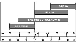
Use oil viscosity based on the expected air temperature range during the period between oil changes.
The following oils are preferred:
Other oils may be used if above John Deere oils are not available, provided they meet one of the following specifications:
• API Service Classification SF, SG, SH or SJ
Checking Engine Oil Level
NOTE: Check oil twice a day if you run engine over 4 hours in a day.
Make sure engine is cold when checking engine oil level.
1. Park machine safely. (See Parking Safely in the SAFETY Section.)
3. Clean area around dipstick prior to removing it.
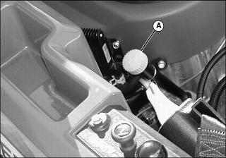
Picture Note: Dipstick in similar location on all models.
4. Remove dipstick (A) from tube by unscrewing it. Wipe it clean.
5. Install dipstick in tube, but do not screw on to threads.
6. Remove dipstick. Check oil level on dipstick; oil level should be between the ADD and FULL marks.
• If oil is low, add oil to bring oil level no higher than the FULL mark on dipstick.
• If oil level is above the FULL mark, drain to proper level.
7. Install dipstick and tighten.
Changing Engine Oil and Filter
IMPORTANT: Avoid damage! Change the oil more often if the vehicle is used in extreme conditions: |
2. Park machine safely on a level surface. (See Parking Safely in the SAFETY section.)
3. Put container under oil drain area.
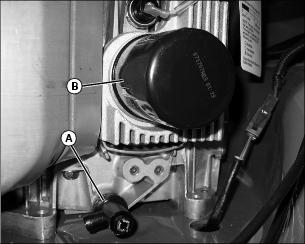
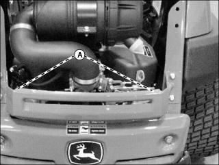
4. Open oil drain plug (A) and allow oil to drain.
5. After oil drains close the drain plug and remove the oil filter (B).
6. Apply a film of clean engine oil on gasket of new filter.
7. Install filter. Turn filter clockwise until gasket makes contact with mounting surface. Tighten by hand 3/4 turn more after gasket contact.
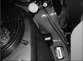
8. Clean area around the oil dipstick (C).
9. Unscrew and remove the dipstick.
11. Install and tighten dipstick.
12. Start engine and run at slow throttle for approximately two minutes. Check for leaks around filter and drain plug.
• Remove and wipe dipstick clean with a rag.
• Install dipstick but do not screw onto threads.
• Remove dipstick. Check oil level on dipstick; oil level should be between the ADD and FULL marks. Add oil if needed.
15. Install dipstick and tighten.
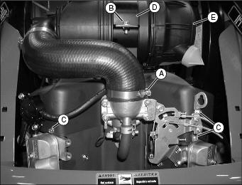
Checking and Replacing Air Cleaner Element
IMPORTANT: Avoid damage! Dirt and debris can enter the engine when removing the air cleaner elements. Service elements only at prescribed intervals. |
1. Park the machine safely. (See Parking Safely in the SAFETY section.)
Picture Note: Your model may be different from the model shown.
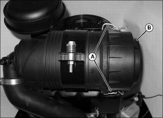
2. Unhook latches (A) and remove cover (B).
Picture Note: Your model may be different from the model shown.
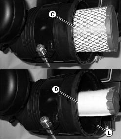
3. Remove primary element (C) and secondary element (D).
NOTE: The air cleaner elements are not recommended to be cleaned.
• Do not wash air cleaner elements.
• Do not oil air cleaner elements.
• Do not use pressurized air to clean air cleaner elements.
4. Inspect air cleaner elements and replace if dirty or at specified intervals
• Replace the secondary element if dirty when the primary element is checked and replaced.
5. Clean the housing (E) with detergent and water. Dry thoroughly with a clean cloth.
NOTE: If the housing is damaged, it must be replaced.
6. Check the housing for deformation or other damage. The housing must seal well and permit only filtered air to reach the carburetor.
7. Check that no foreign material is obstructing the air passage.
9. Replace cover with the “up” mark on the cover at the twelve o’clock position and secure latches.
Checking Spark Plugs
1. Park machine safely. (See Parking Safely in the SAFETY section.)
2. Clean area around both spark plugs.
3. Disconnect the spark plug wire (A) from each plug.
4. Remove and inspect spark plugs:
• Clean each plug and check for damage, replace if necessary.
• If plugs are in good condition, check gap.
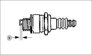
5. Check and adjust spark plug gap (B) to 0.76 mm (0.030 in.).
• Tighten to 22 N•m (16 ft-lb).
7. Install both spark plug wires.
Cleaning Debris From Engine (Models Z910A and Z920A)
• Clear work area of bystanders. • Wear eye protection when using compressed air for cleaning purposes. |
1. Park machine safely. (See Parking Safely in the SAFETY section.)
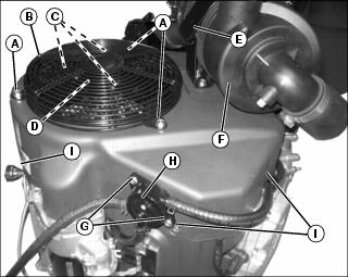
3. Loosen and remove three hex socket head bolts (A) and remove fan screen guard (B).
4. Remove three hex head bolts (C) and remove fan screen (D).
5. Open air cleaner latch (E) and remove air cleaner assembly (F) from top of engine.
6. Remove two hex head bolts (G) and remove fuel pump (H).
7. Remove six engine shroud hex head bolts (I).
8. Lift shroud (I) upward and remove from engine compartment.
9. Clean debris from engine area and all engine cooling fins.
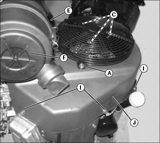
Cleaning Debris From Engine (Models Z925A, Z930A, Z950A, Z960A, and Z970A)
• Clear work area of bystanders. • Wear eye protection when using compressed air for cleaning purposes. |
NOTE: Your model may be different from the model shown.
1. Park machine safely. (See Parking Safely in the SAFETY section.)
2. Allow machine to cool down.
3. Loosen clamp (A), remove hex head bolts (B) and (C).
4. Lift bracket (D) and pivot air cleaner assembly (E) out leaving the intake hose connected.
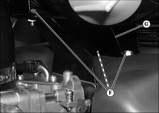
5. Remove the three hex head bolts (F) and air cleaner bracket (G).
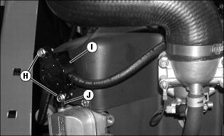
6. Remove the two hex head bolts (H) fuel pump (I) and disconnect the vacuum hose (J).
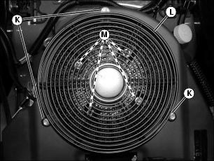
7. Remove the three hex head bolts (K) and fan shroud (L).
8. Remove the four hex socket head bolts (M) and the fan screen.
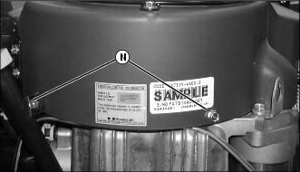
9. Remove the engine shroud bolts (N).
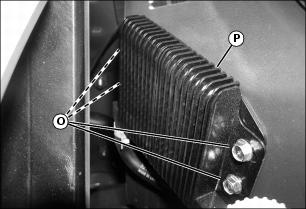
10. Remove the four hex head bolts (O) and remove oil cooler (P).
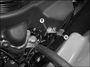
11. Z925A, Z930A and Z950A: Loosen the top hex head bolts (Q) to the voltage regulator (R).
13. Clean the debris from the engine area and all engine cooling fins.
15. Tighten voltage regulator top bolt.
18. Install fuel pump and connect vacuum hose.
19. Install air cleaner bracket.
20. Pivot air cleaner to proper position and tighten hardware.
Replacing Fuel Filter
NOTE: Change fuel filter when fuel is low.
1. Park machine safely. (See Parking Safely in the SAFETY section.)
3. Place a drain pan under hoses to catch any fuel that may be left in the hoses.
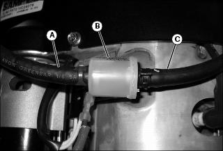
4. Disconnect fuel hose (A) from the outlet side of the fuel filter (B), and drain gasoline into a properly marked container.
5. Remove the fuel filter from the inlet fuel hose (C). Discard filter.
• Make sure fuel filter is installed with arrow pointing in direction of fuel flow.
7. Connect hoses to new fuel filter.
Adjusting Carburetor
NOTE: Carburetor is calibrated by the engine manufacturer and is not adjustable.
If engine is operated at altitudes above 1829 m (6,000 ft), some carburetors may require a special high altitude main jet. See your authorized dealer.
If engine is hard to start or runs rough, check the TROUBLESHOOTING section of this manual.
Possible engine surging will occur at high throttle with transmission in N neutral and mower engagement lever disengaged. This is a normal condition due to the emission control system.
After performing the checks in the troubleshooting section and your engine is still not performing correctly, contact your authorized dealer.