
Installing
Removing Rear Bumper Weight
1. Park machine safely. (See Parking Safely in the Safety section.)
2. Open the engine cover by turning the latch handle counter-clockwise and sliding the cover rearward until it stops.
3. Remove hood - Early Models:
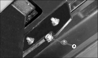
Picture Note: Early Model Shown
• Remove cap screw (A) from inside edge of engine cover slides, on left and right side of machine.
• Pull engine cover rearward until it can be removed from machine.

• Remove two spring pins (B) and lower hood to ground with cable still attached.
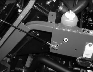
• Remove spring pin (C) and slide cable away from clevis pin.
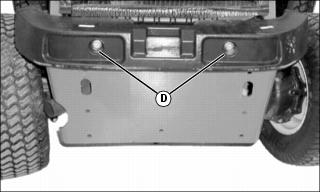
Picture Note: Early Model Shown
5. Remove two bolts (D) and nuts securing bumper to machine.
Removing Side Fender
Early Models
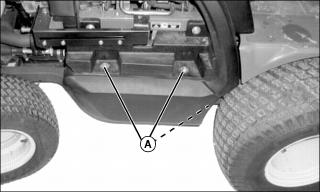
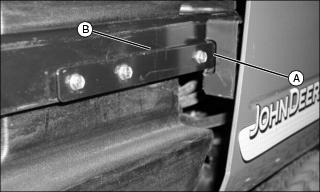
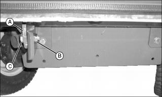
1. Remove three bolts and washers (A) securing right side fender to the machine.
Series II
1. Remove right-side outer metal panel.
2. Remove two bolts (B). Remove two bolts and washers (C).
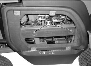
4. Cut off lower part of panel just below lower clips at location shown.
Install side panel and outer metal panel after drive line is installed.
Picture Note: Side panel will look similar to this with MCS installed.
Installing Driveline
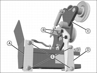
1. Remove plates (A)(D) from the driveline and idler arm assembly by removing nuts, bolts and washers (E).
2. Remove idler arm assembly (C) from the driveline.
3. Install driveline on the machine.
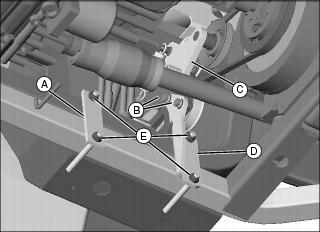
4. Install plate (A) with two nuts (E).
5. Install plate (D) with two nuts (E) and two bolts and washers (B) to secure the driveline to the machine and idler arm assembly.
6. Align driveline double pulley with pulley on flywheel using a long straight shaft.
7. Install idler arm assembly (C) on driveline.
IMPORTANT: Avoid damage! Check that the driveline pulleys align properly with the flywheel pulley to prevent belt damage and wear. |
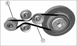
8. Install belt (F) on driveline pulley (E). Verify that belt is installed correctly and properly aligned.
Installing Double Spool Hydraulic Kit
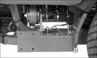
Install the Double Spool Hydraulic Kit according to the instructions that are supplied with the kit, except for the installation of the auxiliary valve. Use the valve retaining bracket (A) instead of the valve bracket provided with the kit.
Installing Back -Up Alarm and Switch
Install Back-Up Alarm
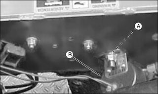
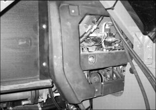
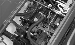
1. Remove nut and screw from hole (A) on the right side of the engine compartment.
2. Install back-up alarm (B) as shown, using screw and nut.
Install Back-Up Switch
2. Locate and remove two bolts (A).

Picture Note: Picture shows only the switch bracket for illustration clarity.
3. Install back-up alarm switch bracket (B) to machine with bolts (A), washer (E) and bushings (C) as shown.
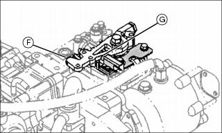
4. Verify that the button (G) on switch is engaged by the reverse arm (F) when the reverse pedal is depressed. Adjust the position of the switch by moving hardware in hole (D).
Installing Wiring Harness
1. Disconnect negative (black) battery cable.
IMPORTANT: Avoid damage! Route wiring harness connections away from moving parts and pinch points. Use tie straps to secure harness to machine to prevent damage. |
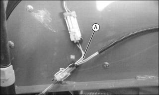
2. Install the pink and yellow jumper wire (A) on the seat switch connection.
NOTE: MCS switch might be installed in an alternate location if the optional cruise control is installed.
Picture Note: Early Model Shown
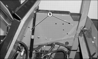
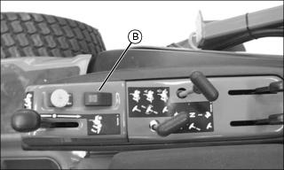
3. Route the purple, pink, gray and white wires for the MCS rocker switch (B) up under the operator’s console and install the MCS switch with the red button towards the front of the machine as shown.
4. Mount the relay inside the frame near the machine relays. Use the screw from the first machine relay to secure the MCS relay to the machine.
5. Route the purple, white and orange wire with the white connector toward the brake switch. Install connector on brake switch.
6. Route the green and brown wires (with bulb) to steering column and install.
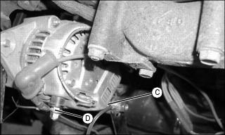
7. Route the red and brown wires following the same routing as the main machine wiring harness. Connect the brown wire ring terminal to ground (C) as shown. Connect Red wire to alternator terminal (D) as shown and install boot on terminal
8. Route the MCS electrical connection wire down toward the driveline, to connect when the MCS is installed.
9. Route the blue and yellow wire to the back-up alarm switch and connect to switch.
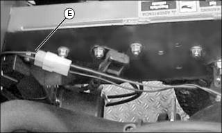
10. Route the blue and brown wire (E) to the back-up alarm and connect to alarm as shown.
11. Connect negative (black) battery cable.
Installing Engine Cover
Early Models
1. Line up slides (A) on inside of engine cover with rails (B) on left and right side of machine.
2. Push the engine cover onto the rails until top edge of engine cover is over radiator cap.
3. Install stop cap screws into engine cover slides on left and right side of machine.
4. Close engine cover, then turn latch handle clockwise to latch.
5. Insert key in slot and turn clockwise to lock engine cover.
Series II
1. Carefully place hood on ground behind machine.

2. Install cable on clevis pin and retain with spring pin (A).
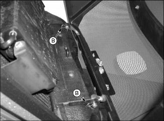
3. Lift hood into place and insert hinge into brackets. Install two spring pins (B).
Installing MCS Using Hoist
IMPORTANT: Avoid damage! If the attachment is installed using a hoist, use belts rather than chains or cables to prevent damage to the attachment. |
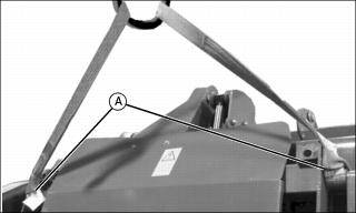
Install MCS using a hoist Secure lifting straps to points (A).
Installing MCS
NOTE: Leave hardware loose during installation.
1. Carefully back machine up to MCS.
2. Park machine safely. (See Parking Safely in the Safety section.)
3. Attach MCS to rear of machine at the rear by aligning holes in MCS frame (A) with holes in rear brackets and securing with bolts (C) and nuts (B).
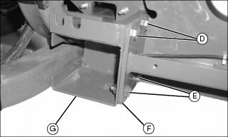
4. Attach blower housing (F) to driveline (G) by lining up the four holes on driveline with the holes on the blower housing. Secure using locknuts and two M10x35 bolts (D) and two M10x25 bolts (E).
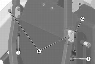
5. Attach MCS to ROPS brackets by lining up holes in MCS frame with holes on brackets. Insert the spacers (G) between the bracket and the MCS. Secure with M20x100 bolts and M20 lockwashers (H).
6. Adjust bolts (I) to rest against ROPS frame.
7. Tighten all hardware securing MCS to machine.
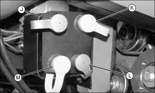
8. Remove dust covers from three ports (J, L, and M). Upper front port (K) is not used.
IMPORTANT: Avoid damage! Check to make sure all hydraulic hoses are routed away from moving parts and pinch points. Use tie straps to secure hoses to machine to prevent damage. |
9. Connect hydraulic hoses from MCS to machine.
• Connect the female coupler from the lift cylinder to the lower front port (L).
• Connect the male coupler from the smaller cylinder to the lower rear port (M).
• Connect the female coupler from the smaller cylinder to the upper rear port (J).
10. Connect the MCS electrical connection, located in the blower housing to the connection on the wiring harness.
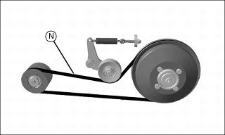
11. Install the fan belt (N). Verify that the belt is routed correctly.
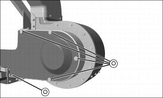
13. Install the fan belt shield using five screws (O).
14. Verify that all hardware connecting MCS to machine has been tightened.
Installing Boot and Hose
1. Remove discharge chute from mower deck.
2. Clean grass and dirt from mower deck opening.
3. Install boot retaining bracket to deck using two bolts.
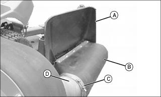
4. Fasten boot (B) to mower deck with long pin and quick connect pin.
5. Install discharge chute (A).
6. Install clamps (C) on both ends of hose (D).
IMPORTANT: Avoid damage! To prevent damage to the hose, the hose must not contact the ground or interfere with the front wheel. Shorten the hose, if necessary. |
7. Install hose on boot and fan. Secure with clamps.
Testing the Park Brake
After the MCS is installed on the machine, check the brakes.
1. Stop machine on a 17? slope (30% grade). Stop the engine and lock the park brake.
Testing the PTO Switch
1. Sit on the seat. (Seat should spring down slightly so seat switch is actuated.)
3. Pull PTO knob up to the on position.
4. Turn key to start position.
5. Unlock the park brake (keep PTO engaged). Try to start engine.
Check Operation of the Back -Up Alarm
2. Make sure hydrostatic travel pedals are in the neutral position and the park brake is locked.
5. Depress reverse travel pedal slightly. The back-up alarm should sound.
• If the alarm is sounding before the reverse travel pedal is depressed, adjust the switch rearward.
• If the alarm fails to sound after the reverse travel pedal is depressed, adjust the switch forward.