
Service Electrical
Battery Warning
Service the Battery Safely
Checking Battery Electrolyte Level
NOTE: Add only distilled water to replace battery electrolyte.
1. Park the machine safely. (See Parking Safely in the SAFETY section.)
2. Remove battery cell caps. Make sure cap vents are not plugged.
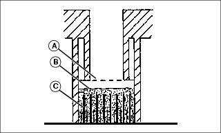
3. Check electrolyte level. Electrolyte (B) should be approximately halfway between bottom of filler neck (A) and top of plates (C).
IMPORTANT: Avoid damage! Do not overfill battery. Electrolyte can overflow when battery is charged and cause damage. |
4. Add only distilled water if necessary.
Removing and Installing Battery
Removing:
1. Park machine safely. (See Parking Safely in the SAFETY Section.)

3. Disconnect negative (-) battery cable (A).
4. Push red cover (B) back away from positive (+) battery cable and remove cable from battery.
5. Loosen bolts (C) and remove battery compartment hold- down brackets (D).
Installing:
1. Install battery into machine.
2. Connect positive (+) cable to battery positive (+) terminal first, then negative (-) cable to battery negative (-) terminal.
3. Apply spray lubricant to terminals to prevent corrosion.
4. Slide red cover over positive battery cable.
5. Install battery compartment hold-down brackets and bolts. Do not overtighten.
Cleaning Battery and Terminals
1. Park machine safely. (See Parking Safely in the SAFETY section.)
2. Disconnect and remove battery.
3. Wash battery with solution of four tablespoons of baking soda to one gallon of water. Be careful not to get the soda solution into the cells.
4. Rinse the battery with plain water and dry.
5. Clean terminals and battery cable ends with wire brush until bright.
7. Attach cables to battery terminals, beginning with the positive cable, using washers and nuts.
8. Apply spray lubricant to terminal to prevent corrosion.
Using Booster Battery
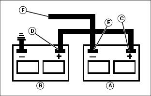
1. Connect positive (+) booster cable to booster battery (A) positive (+) post (C).
2. Connect the other end of positive (+) booster cable to the disabled vehicle battery (B) positive (+) post (D).
3. Connect negative (-) booster cable to booster battery negative (-) post (E).
4. Connect the other end (F) of negative (-) booster cable to a metal part of the disabled machine engine block away from battery.
5. Start the engine of the disabled machine and run machine for several minutes.
6. Carefully disconnect the booster cables in the exact reverse order: negative cable first and then the positive cable.
Replacing Headlight Bulb
1. Park machine safely. (See Parking Safely in the SAFETY section.)
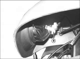
3. Disconnect wire harness (A) from defective headlight bulb assembly.
4. Rotate bulb assembly (B) to remove from housing socket.
NOTE: Do not touch the new bulb assembly with bare hands. Use a clean cloth to install, and hold the bulb only by the connector.
5. Install new bulb assembly into housing socket and rotate to lock in place.
6. Connect wire harness to bulb assembly.
7. Check operation of headlights.
Replacing Light Bulbs (Tractor With Cab)
Dome Light Bulb
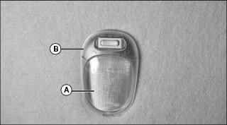
1. Remove cover (A) from housing (B) using a screwdriver.
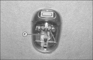
3. Install new bulb and cover.
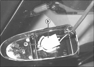
Taillight Bulb

Picture Note: Left rear shown.
1. Remove four screws and cover (A) under fender.
2. Rotate socket (B) and remove from housing.
3. Install new bulb and socket in housing.
4. Install cover and screws to fender.
Rotary Beacon Light Bulb
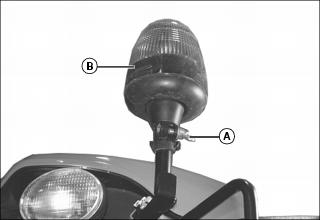
1. Loosen wing nut (A) and remove rotary beacon light assembly.
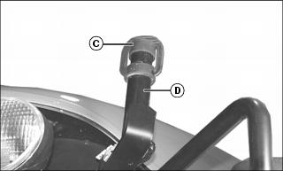
2. Install rubber cab (C) on mounting shaft (D).
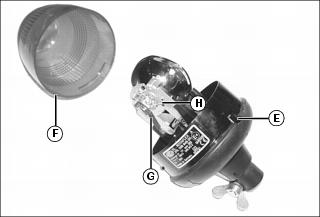
3. Depress tab (E) and rotate lens (F) counterclockwise to remove.
4. Pull tab (G) away from bulb.
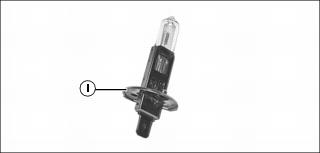
5. Unlatch retaining spring (H) and remove light bulb (I).
6. Install new bulb in reverse order of removal.
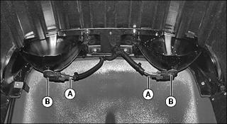
Warning Light Bulb
NOTE: Bulb replacement procedures for front and rear warning lights are similar. On rear warning light, bracket for the work light is also removed when removing two screws. Front right side shown.
1. Remove two hex socket head screws (A) and lens assembly (B) from cab roof panel.
2. Push in tab (C) and rotate socket (D) counterclockwise to remove from housing. Install new bulb into socket.
3. Install socket, and rotate clockwise to lock tab into position.
4. Install housing with two hex socket head screws.
Work Light Bulb
NOTE: Bulb replacement procedures for front and rear work lights and optional auxiliary work lights are the same. Rear left side shown.

1. Disconnect wiring harness connector (A).
2. Rotate bulb base (B) counterclockwise and remove from housing.
3. Install new bulb into housing and rotate bulb base clockwise to install.
4. Connect wiring harness connector.
Replacing Light Bulbs (Tractor Without Cab)
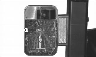
Replacing Taillight Bulb
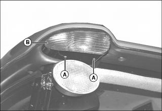
1. Park machine safely. (See Parking Safely in the SAFETY section.)

2. Remove two screws (A) and lens (B).
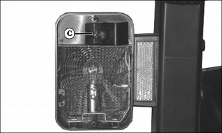
3. Pull bulb (C) straight out to remove. Do not twist bulb.
5. Check operation of taillights.
Replacing Warning Light Bulb
1. Park machine safely. (See Parking Safely in the SAFETY section.)
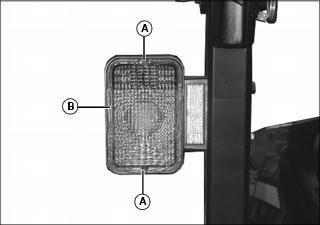
2. Remove two screws (A) and lens (B).
3. Push down and rotate bulb (C) to remove. Do not twist bulb.
4. Push down and rotate new bulb into socket.
5. Check operation of warning lights.
Replacing Fuses and Relays
IMPORTANT: Avoid damage! The electrical system may be damaged if incorrect replacement fuses are used. Replace the bad fuse with a fuse of the same amp rating. |
Machines Without Cabs
1. Park machine safely. (See Parking Safely in the SAFETY section.)
2. Lower load center access cover (A).
3. Fuse and relay identification:
4. Pull defective fuse or relay from socket.
5. Push new fuse or relay into socket.
6. Install fuse block access cover.
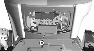
Machines With Cabs
1. Park machine safely. (See Parking Safely in the SAFETY section.)
2. Pull forward and out on the access cover (A) to remove the cover.
3. Fuse and relay identification:
4. Pull defective fuse or relay from socket.
5. Push new fuse or relay into socket.
6. Install fuse block access cover.
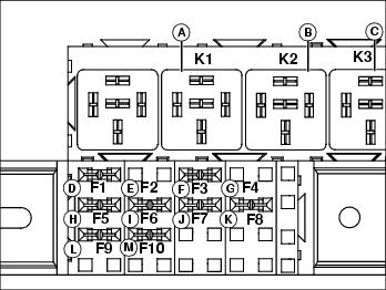
I Rear Outlet SCV Load Center Fuse and Relay Identification (Open Station Models)
1. Park machine safely. (See Parking Safely in the SAFETY section.)

2. The I Rear Outlet load center is located on the rear of the machine. Lift the cover (A) for access to the fuses and relays.
3. Fuse and relay identification:
4. Pull defective fuse or relay from socket.
5. Push new fuse or relay into socket.
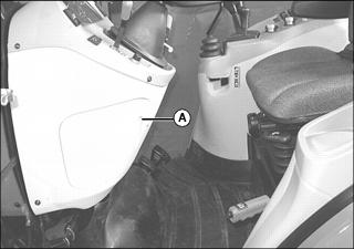
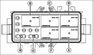
I Rear Outlet SCV Load Center Fuse and Relay Identification (Cab models)
1. Park machine safely. (See Parking Safely in the SAFETY section.)
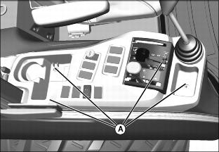
2. The load center is located below the right console cover. Remove four screws (A) and lift the cover as required for access.
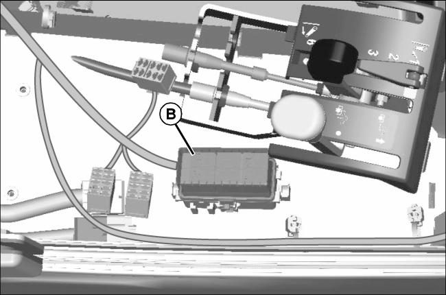
Picture Note: cover removed for better view.
3. Lift the load center cover (B) for access to the fuses and relays.
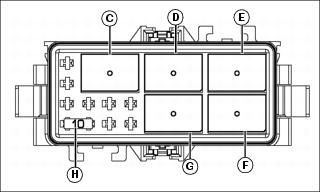
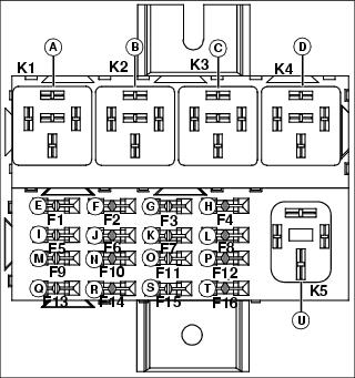
4. Fuse and relay identification:
5. Pull defective fuse or relay from socket.