
Assembly
Parts in Kit
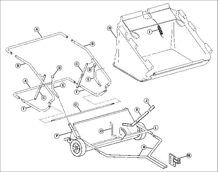
Hardware (Skin Pack)
Hardware (Bag of Parts)
Assemble Front Frame and Lift Assembly
NOTE: Use hardware from skin pack for this sequence.
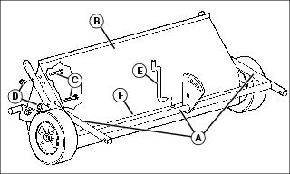
1. Align the upper frame assembly (A) with the brush housing assembly (B) and secure on each side with two 5/16 x 1-1/2 in. carriage bolts (C) (installed from the inside, as shown) and 5/16 in. nylock nuts (D). Tighten hardware.
2. Insert lift link (E) into hole in cross tube (F), oriented as shown
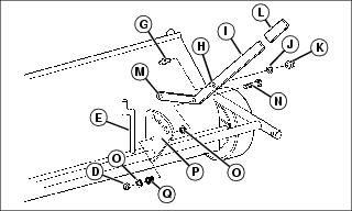
3. Insert the threaded end of lock pin (G) into upper hole (H) in lift handle (I) and secure using a 5/16 in. lock washer (J) and 5/16 in. standard nut (K).
4. Install the flat grip (L) on the end of the lift handle.
5. Rotate the lift handle and assemble it to the lift link (E) through the lower hole (M).
6. Install a 5/16 x 1-3/4 in. hex bolt (N) through the middle hole in the lift handle (I), then install a 5/16 in. flat washer (O) onto the hex bolt on the other side of the lift handle, as shown.
7. Align the lift handle against the lock plate (P), with the lock pin in one of the seven index holes at the top of the lock plate and the hex bolt through the lower hole. Secure with spring (Q), 5/16 in. flat washer (O) and 5/16 in. nylock nut (D). Tighten lock nut, then back off as necessary for proper operation.
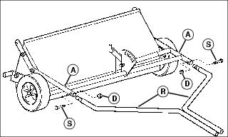
8. Install the two tow tubes (R) into the upper frame assembly (A), and secure with two 5/16 x 1-1/2 in. hex bolts (S) inserted from the outside, and 5/16 in. nylock nuts (D) at the inside. Tighten hardware only finger-tight at this time.
Assemble Hitch Components
NOTE: Use hardware from skin pack for this sequence.
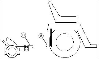
1. Park machine on a level, hard surface and measure from the ground to the top of the rear hitch plate (A) or drawbar. This measurement will determine mounting position of hitch clevis assembly (B).
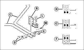
Picture Note: Hitch clevis at bottom.
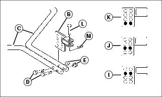
Picture Note: Hitch clevis at top.
2. Place hitch clevis assembly (B) between the two tow tubes (C) and secure with two 5/16 x 2-1/4 in hex bolts (D) and 5/16 in. nylock nuts (E). Position hitch clevis and mounting holes as follows according to hitch plate or drawbar height:
a. 15.2 cm (6 in.) - Clevis at bottom, hole position (F).
b. 17.8 cm (7 in.) - Clevis at bottom, hole position (G).
c. 20.3 cm (8 in.) - Clevis at bottom, hole position (H).
d. 22.9 cm (9 in.) - Clevis at top, hole position (I).
e. 25.4 cm (10 in.) - Clevis at top, hole position (J).
f. 27.9 cm (11 in.) - Clevis at top, hole position (K).
3. Tighten hitch clevis hardware and hardware securing tow tubes to upper frame.
4. Insert hitch pin (L) into hitch clevis and secure with large hairpin cotter (M) to store until needed.
Assemble Hamper Components
NOTE: Use hardware from skin pack and bag of parts for this sequence.
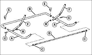
1. Install two lower tubes (A) into one of the rear tubes (B). Align curved ends of lower tubes upward, as shown, when assembling components.
2. Thread a 3/8 in. standard nut (C) approximately 19 mm (3/4 in.) onto each end of hamper stop rod (D), then assemble the stop rod between the two lower tubes.
3. Secure lower tubes to rear tube with 5/16 x 5/8 in. push connector (E).
4. Assemble a spreader bar assembly (F) at the inside of each lower tube, with the shorter legs toward the hamper bottom. The hinged spreader bars should be installed so that the hinge pivots to the front as they are collapsed for storage, as shown. Secure with 1/4 x 1-1/4 in. screws (G) installed from the outside and 1/4 in. locknuts (H) at the inside.
NOTE: Flip attached windscreen behind hamper during hamper component assembly.
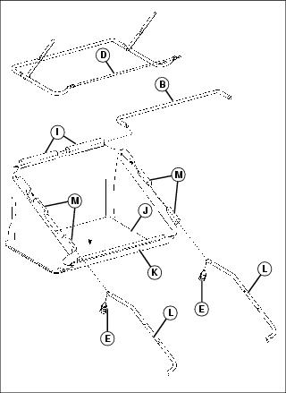
5. Feed the remaining rear tube (B) carefully through the sewn pockets (I) at the rear of the hamper. The material will have to be bunched together as the tube is fed through.
6. Place the previously assembled lower tubes, rear tube, spreader bars and hamper stop rod into the bottom of the hamper and adjust to fit tightly against the hamper base (J).
7. Lift the front of the hamper base with formed plastic channel (K) up over the hamper stop rod (D) and then press it down until it snaps over the hamper stop rod to secure.
8. Insert the straight ends of the upper tubes (L) into the sewn pockets (M) at the sides of the hamper and assemble them into the rear tube (B) at the top of the hamper. Position the curved ends of the upper tubes so they point down, as shown, and secure the upper tubes to the rear tube with two 5/16 x 5/8 in. push connectors (E).
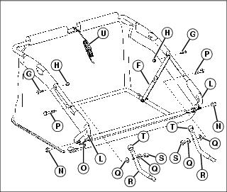
9. Assemble the curved ends of the upper tubes (L) over the ends of the hamper stop rod and secure with 3/8 in. locknuts (N).
10. Engage snaps (O) at each corner of the hamper.
11. Straighten and lock spreader arms (F), then open hamper fully. Assemble the spreader arms to the upper tubes, securing with 1/4 x 1-1/2 in. round head screws (G) from the outside, through existing holes in the sewn pocket of the hamper and upper tube, and 1/4 in. locknuts (H) on the inside.
12. Insert a 5/16 x 2-1/2 in hex bolt (P), from the outside, through an existing hole in each upper tube in an area exposed by a cutout in the sewn pocket of the hamper.
NOTE: If two mounting holes are present at the curved end of the hamper mount tubes, install the hex bolt through the lower hole.
13. Assemble a 5/16 in. special flat washer (Q) and hamper mount tube (R) on the hex bolt (P) at the inside of each upper tube, securing with a 5/16 in. special flat washer (Q) and 5/16 in. nylock nut (S). Do not overtighten hardware, hamper mount tube must be able to pivot freely.
14. Install a vinyl cap (T) over the pivot end of each hamper mount tube, as shown.
15. Tie hamper pull rope (U) to upper rear tube where sewn pocket of hamper is cut away.
Assemble Hamper to Sweeper
NOTE: Use hardware from bag of parts for this sequence.
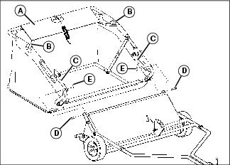
1. Flip windscreen (A) to the front over the top of the hamper and wrap hook and loop fastener strips (B) around upper hamper tube on each side, at first cut-out area, to secure.
2. Insert the end of each hamper mounting tube (C) into the upper frame assembly of the sweeper on each side and secure with 5/16 x 1-3/8 in. clevis pins (D) installed from the outside and small hairpin cotters (E) at the inside.


