
Operating
Daily Operating Checklist
o Check brakes and park brake operation.
o Check area below machine for leaks.
o Check charger and vehicle battery receptacle for damage.
o Visually inspect condition of batteries.
Avoid Damage to Plastic and Painted Surfaces
Do not wipe plastic parts unless rinsed first. Using a dry cloth may cause scratches.
Insect repellent spray may damage plastic and painted surfaces. Do not spray insect repellent near machine.
Be careful not to spill fuel on machine. Fuel may damage surface. Wipe up spilled fuel immediately.
Prolonged exposure to sunlight will damage hood surfaces.
Operator Station Controls
Dash
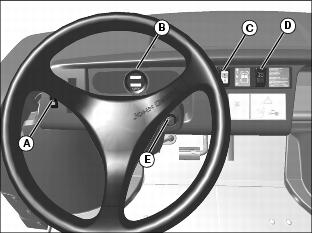
A - Cargo Box Dump Switch (Optional)
C - Directional Control Switch
Foot/Platform Controls
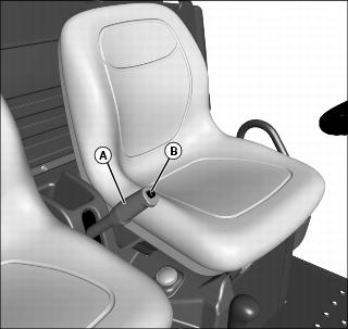
Using Hand Holds
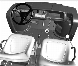
Hand holds are provided for passenger balance. When a passenger is present, they shall use both of the hand holds at all times while the machine is moving: the dash bar (A), and the side rail (B) to the right of the seat.
Adjusting Standard Seat
NOTE: If seat is removed, install seat hardware in the correct slots in the bracket. Always use set of slots closest to center of vehicle when installing seat.
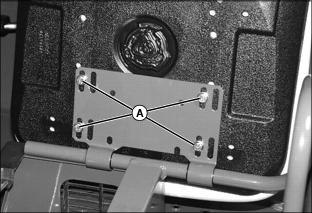
Picture Note: Passenger seat shown.
2. Hold onto seat and loosen cap screws (A).
3. Slide seat forward or rearward for desired position.
4. Tighten seat cap screws to 12.2 Nm (9 lb-ft).
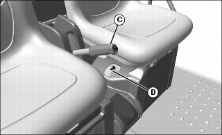
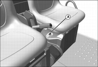
Adjusting Driver Seat With Optional Lever System
1. Stop machine and move transaxle shift lever to the neutral position.
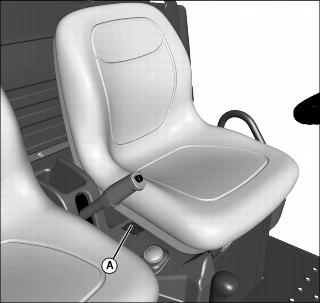
3. Pull up on lever (A), and slide seat forward or rearward until seat locks in place.
Testing Safety Systems
Use the following checkout procedure to check for normal operation of the utility vehicle.
If there is a malfunction during one of these procedures, DO NOT operate the vehicle. (See a John Deere dealer for service.)
Perform these tests in a clear open area. Keep bystanders away.
Test 1 (REVERSE WARNING ALARM)
NOTE: Perform this test with the vehicle parked on a hard, level surface.
1. Move the service/drive switch to the DRIVE position.
2. Sit on the operator's seat.
3. Lock park brake/emergency stop.
4. Turn the key switch to the ON "1" position.
5. Press the directional control switch to the REVERSE position.
The reverse warning alarm should be a continuous tone.
Test 2 (ROLL-AWAY ALARM)
NOTE: Perform this test with the vehicle parked on a hard, level surface.
1. Move the service/drive switch to the DRIVE position.
2. Sit on the operator's seat.
3. Unlock park brake/emergency stop.
4. Turn the key switch to the ON "1" position.
5. Press the directional control switch to the FORWARD position.
6. Roll vehicle forward and rearward slightly.
The vehicle should resist movement and the roll away alarm should begin an intermittent tone.
7. Press the directional control switch to the NEUTRAL position.
8. Roll vehicle forward and rearward slightly.
The vehicle should resist movement and the roll away alarm should begin an intermittent tone.
NOTE: When the directional control switch is placed into REVERSE, the reverse warning alarm a continuous tone will sound.
9. Press the directional control switch to the REVERSE position.
The reverse warning alarm should start a continuous tone.
10. Turn the key switch to the OFF "0" position.
The vehicle should resist movement and the roll away alarm should begin an intermittent tone.
Test 3 (OPERATOR PRESENCE)
1. Move the service/drive switch to the DRIVE position.
2. Sit on the operator's seat.
3. Lock park brake/emergency stop.
4. Turn the key switch to the ON "1" position.
5. Move the directional control switch to the forward or neutral position.
6. Raise from operator's seat.
After approximately two seconds, the alarm should sound a continuous tone.
Test 4 (CHARGER INTERLOCK)
1. Move the service/drive switch to the DRIVE position.
NOTE: It is not necessary to connect the charger AC input plug to an electrical outlet when performing this test.
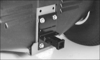
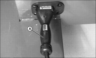
3. Connect the battery charger DC cable plug to the vehicle battery receptacle located below the operator seat on the left side of the vehicle.
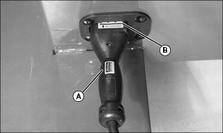
Grasp DC plug handle (A) and push plug straight into receptacle to the full engagement mark (B).
4. Turn the key switch to the ON "1" position.
5. Move the directional control switch to the reverse position.
The reverse warning alarm must not sound.
6. Disconnect the DC cable plug from the vehicle receptacle.
The reverse warning alarm should start a continuous tone.
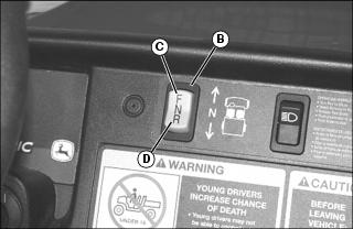
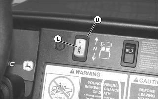
Using the Directional Control Switch
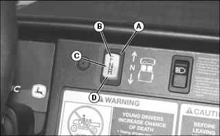
The directional control switch (A) is located on the dash panel. There are three positions:
FORWARD: Press the switch forward to position (B).
NEUTRAL: Press the switch into the middle position (C).
REVERSE: Press the switch downward to position (D).
Using the LED Charge Meter and the Hour Meter
NOTE: Key switch must be turned to the ON "1" position to activate the charge meter LED display.
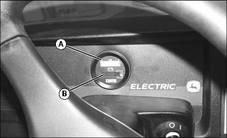
Charge Meter
When activated and during normal operation, the charge meter will continuously monitor the battery charge.
The charge meter (A) has a multi-colored 10-bar LED that displays vehicle state of charge. Only one LED will illuminate at a time.
A double flashing RED 2-bar LED signals "empty" at 80% of battery discharge. This signals to the operator that the battery charge is very low and the vehicle should return to an area where the battery set can be charged.
A double flashing YELLOW 3-bar LED signals "energy reserve" at 70% of battery discharge. This signals to the operator that the battery charge is getting low.
A GREEN 5-bar LED signals that the "energy reserve" is between 50 and 100% of battery charge.
Hour Meter
The hour meter (B) shows the number of hours the vehicle has run.
The service interval chart gives necessary service intervals. Use the hour meter and the service interval chart to determine when the vehicle will need service. (See SERVICE INTERVALS Section.)
Using the LCD Charge Meter and the Hour Meter
NOTE: Key switch must be turned to the ON "1" position to activate the charge meter LCD display.
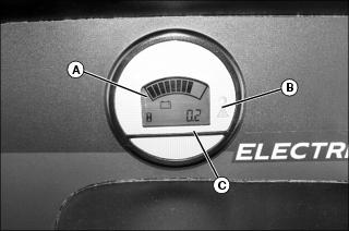
Charge Meter
The charge meter will continuously monitor the battery charge while the drive/service switch is in the drive mode.
The charge meter (A) has a 10-segment bar graph LCD that displays the battery state of charge.
All segments of the bar graph are turned ON when the battery is full. The number of segments turned ON is reduced to indicate a reduced state-of-charge.
The next-to-last segment will flash when the battery is 70% discharged to indicate that the battery charge is getting low and should soon be recharged.
NOTE: Continual discharge of the battery bank beyond the 80% discharge level will significantly reduce the cycle life of the batteries.
The next-to-last segment and the last segment will alternately flash when the battery is 80% discharged. The red LED (B ) will also turn ON at this point to get the operator's immediate attention. The vehicle should not be operated with the batteries at this level except to return it to a location where it can be recharged.
Hour Meter
The hour meter (C) shows the number of hours the vehicle has run.
The service interval chart gives necessary service intervals. Use the hour meter and the service interval chart to determine when the vehicle will need service. (See SERVICE INTERVALS Section.)
Using the Service and Drive Switch
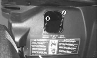
This utility vehicle is equipped with a two position service/drive toggle switch.
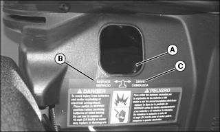
Service Position
When the vehicle service/drive switch (A) is moved to the SERVICE position (B) the vehicle is disabled and prohibited from being driven.
The service/drive switch should be moved to the SERVICE position when:
Performing any service function on the vehicle.
The vehicle is not going to be in service for an extended period of time (one month or more).
Drive Position
When the vehicle service/drive switch (A) is moved to the DRIVE position (C) the vehicle controller is energized. When the key switch is turned to the ON "1" position, controls are energized and the vehicle is ready for normal operation.
Using Park Brake
NOTE: The park brake alarm will buzz if the machine is in gear and you try to move in forward or reverse before unlocking the park brake.
Locking the Park Brake:
1. Push down on brake pedal to hold machine in place.
2. Pull up on lever (A) and lock lever into position engaging park brake.
Unlocking the Park Brake:
1. Push down on brake pedal to hold machine in place.
4. Release lever down completely.
Starting the Vehicle
NOTE: The charger DC cable plug must be removed from the vehicle receptacle before starting the vehicle.
1. Sit on vehicle operator's seat.

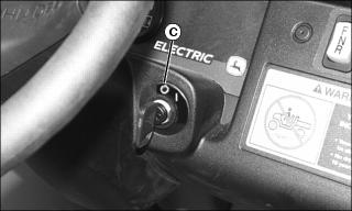
2. Turn key switch to the ON "1" position (A).
NOTE: Reverse warning indicator will sound anytime the key switch is in the ON "1" position and the directional control switch is placed in the reverse position.
3. Select direction of travel.
FORWARD: Press the directional control switch (B) forward to position (C).
REVERSE: Press the directional control switch (B) downward to position (D).
NOTE: An alarm will sound if the key is on, service switch in drive mode, park brake unlocked, machine is shifted into forward, and the operator is off the seat.
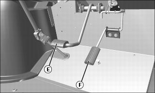
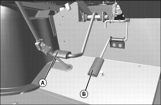
4. Depress the foot brake pedal (E) and release the park brake.
5. Slowly depress accelerator pedal (F) to start vehicle movement.
Stopping and Parking the Vehicle
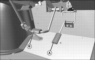
1. Release the accelerator pedal (A) fully and depress the foot brake pedal (B).
2. Allow vehicle to come to a complete stop.
3. Turn key switch to the OFF "0" position (C).
4. Press directional control switch (D) into the center NEUTRAL "N" position (E).
Using the Cargo Box
Raising and Lowering with Manual Lift
1. Park the vehicle safely. (See Parking Safely in the SAFETY section.)
3. Disengage cargo box lock if installed.
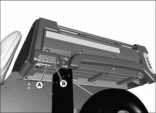
4. Release latch (A) by pulling latch towards grip (B) on cargo box. Allow lift cylinder to raise cargo box.
Raising and Lowering with Power Lift
1. Park the vehicle safely. (See Parking Safely in the SAFETY section.)
2. Disengage cargo box lock if installed.
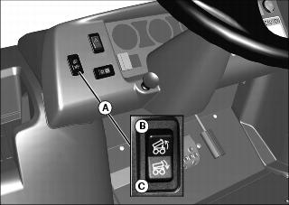
4. The cargo box switch (A) is located on the left side of the instrument panel.
5. Raise cargo box by pressing and holding top of rocker switch (B). Release switch when box is at desired dump height or when reaching maximum height.
NOTE: Allowing the Power Lift actuator clutch to slip briefly (click or ratchet) after cargo box is fully lowered will help keep cargo box secure and reduce rattling caused by travel vibrations.
6. Completely lower cargo box by pressing and holding bottom of rocker switch (C).
Locking Box in Raised Position
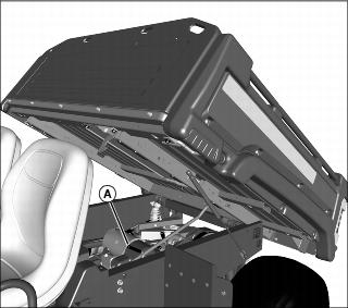
2. Pull down on the cargo box slightly and push rod (A) in toward center of box to locked position.
3. Check to be sure box is locked in raised position.
4. To lower cargo box, lift rod up and slowly push cargo box downward until it latches in fully lowered position.
Operating the Tailgate
Check condition of lanyards for wear or damage. Replace if cable is kinked or frayed. |
1. Check to be sure lanyards (A) are in place to support lowered tailgate.
2. Disconnect lanyards if you want to lower tailgate more than 90 degrees.
IMPORTANT: Avoid damage! Lower tailgate completely to unload cargo box only. Never drive with the tailgate hanging down. Tailgate can contact tires and cause damage. |
3. Pull back on handle (B) to unlock and lower tailgate.
4. Before raising tailgate, check for stones and debris caught in the gap between the tailgate and cargo box floor. To remove debris:
a. Lock the cargo box in raised position.
b. Rotate the tailgate slightly to free debris, and brush out the gap.
5. To raise tailgate, slowly push tailgate upward and lock into closed position.
6. Check to be sure tailgate is securely locked.
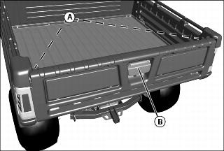
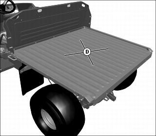
Using Cargo Box Tie Downs
1. Arrange load so the weight is centered over the main cargo area (A).
2. Secure loads to the tie downs (B) in a safe and secure manner.
Removing the Tailgate

1. Check to be sure lanyards (A) are in place to support lowered tailgate.
2. Pull back on handle (B) to unlock and lower tailgate (C).
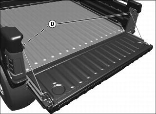
3. Loosen loop (D) on top of lanyards, disconnect from studs on cargo box side, and lower tailgate fully downward.
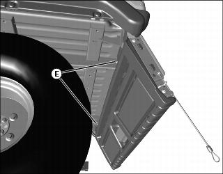
4. Loosen two nuts (E) on rear of floor panel, to allow side panels to be removed.
5. If equipped with taillights, disconnect the wiring harness and hang the harness in the rear of the box.
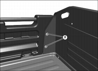
6. From behind driver's seat in cargo box, remove two nuts (F).
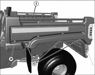
7. Loosen three bolts (G) in left side body panel (H). Do not completely remove bolts from clamp-on nuts.
8. Support the tailgate to avoid bushing damage. Move side body panel slightly outward and remove tailgate from left side body panel and right side body panel (I).
9. Install in reverse order of removal.
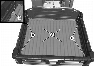
Operating in Flat Bed Mode
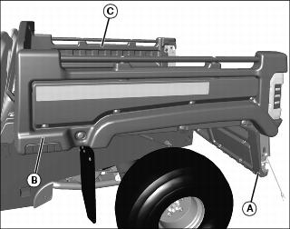
1. To operate machine in flat bed mode, remove tailgate (A) (See Removing the Tailgate).
2. Remove left (B) and right (C) side body panels.
3. Arrange load so the weight is centered over the main cargo area (D).
4. Install tailgate and side panels in reverse order of removal procedure (See Removing the Tailgate).
Loading the Cargo Box
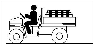
Maximum payload capacity on level terrain for the cargo box is:
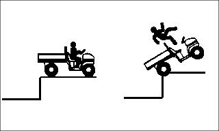
Reduce load by half when operating over rough, hilly, or steep terrain. Do not overload vehicle. Limit loads to those that can be safely controlled.
Reduce speed and exercise extreme caution when operating over rough, hilly, or steep terrain.
Securely anchor and evenly distribute loads in cargo box, when loading objects into vehicle. Shifting loads will affect stability.

Avoid concentrated loads at rear or side of cargo box to prevent vehicle from tipping over. Be sure load is evenly distributed.
Because there is a big difference in weight between dry and wet sand, the only way of getting true weight of the load you are carrying is by using a scale.
Printed weight is normally on bagged and other material.
Box Volume Capacity
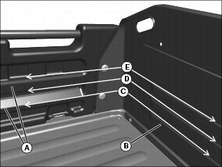
Use rub rails (A) in left and right side panels, and form beads (B) in cargo box front panel to determine cargo box volume.
101 cm (4 in.) load height (C) = 150 L (5.3 cu ft).
152 cm (6 in.) load height (D) = 226 L (8 cu ft).
203 cm (8 in.) load height (E) = 303 L (10.7 cu ft).
NOTE: Use table below to determine height of common cargo box materials.
Emptying Cargo Box
1. Back up vehicle to dump site.
2. Park the vehicle safely. (See Parking Safely in the SAFETY section.)
IMPORTANT: Avoid damage! Stop emptying immediately if actuator clutch slippage occurs. Lower cargo box completely and remove excess load by hand before dumping. |
4. Raise cargo box to dump load.
5. Lower cargo box when empty.
6. Close tailgate. Do not drive vehicle with cargo box in raised position.
Towing Loads
Be sure to load cargo box of utility vehicle before towing a load.
DO NOT tow a load with this vehicle that exceeds 227 kg (500 lb).
DO NOT exceed a tongue weight of 45 kg (100 lb).
Never exceed 16 km/h (10 mph) when towing a load. Tow load at a speed slow enough to maintain control.
Always use hitch point provided on, and hitches approved for, the utility vehicle. They are the approved hitch point and hitches. DO NOT modify in any way.
Using Correct Tires and Inflation
See tire descriptions and inflation pressures in SPECIFICATIONS.
Tires
Use of John Deere approved original equipment or optional equipment is recommended. To ensure maximum machine performance and ride quality, do not mix size, type, or placement of tires. Failure to place tires per the guidelines could result in reduced machine performance, diminished traction and poor handling.
Inflation
IMPORTANT: Avoid damage! Over inflation may damage tires and diminish ride quality. Under inflation could cause wheel damage when riding over rough terrain. |
An accurate low pressure gauge is available at your John Deere dealer.
Towing the Utility Vehicle
IMPORTANT: Avoid damage! Do not tow utility vehicle in excess of 24 km/h (15 mph) or motor may rupture or disintegrate. |
NOTE: When the service/drive switch is moved to the SERVICE position the utility vehicle can be towed with the directional control switch in any position.
1. Move the service/drive switch (A) to the SERVICE position (B) before towing the utility vehicle. (See Using the Service/Drive Switch in this section.)
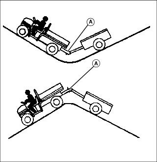
2. Attach a tow line to the utility vehicle.
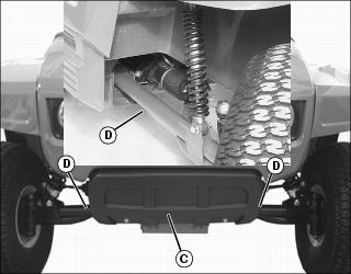
If equipped with the optional front bumper, attach the tow line securely to the front bumper mounting assembly (C).
If vehicle is not equipped with a front bumper, attach the tow line inside the front axle (D) in the position shown.
4. Tow vehicle slowly and carefully to desired location.
Transporting the Utility Vehicle
NOTE: Space limitations may vary from one truck manufacturer to another. Short bed trucks do not have the necessary length requirement to accommodate the vehicle. Vehicle width to outside of tires is 1524 mm (60 in.).
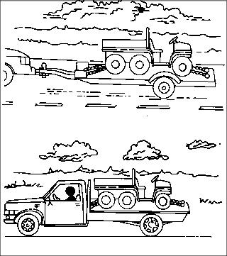
Use a heavy-duty trailer, full size pick-up or flatbed truck to transport the utility vehicle.
Turn key switch to the off "O" position.
Press directional control switch into the NEUTRAL "N" position.
Fasten machine to trailer with heavy-duty straps, chains, or cables. Both front and rear straps must be directed down and outward from the vehicle.
Trailer or truck must have signs and lights required by law.
Use Care In Handling and Servicing Batteries

Prevent Battery Explosions
Batteries contain sulfuric acid and produce explosive mixtures of hydrogen. Because hydrogen gas is present even when the utility vehicle is not in operation, make sure batteries are stored and serviced in a well ventilated area.
Always wear proper eye, face and hand protection.
Keep sparks, lighted matches, and open flame away from the top of battery.
Remove all jewelry (watches, rings, bracelets, etc.) before servicing the electrical system or batteries.
Make sure work area is well ventilated.
Never lean over battery while testing or charging.
Keep removable vents tight and level except when servicing electrolyte.
Exercise caution while working with tools or conductors to prevent short circuits and sparks.
Never check battery charge by placing a metal object across the posts. Use a battery tester, voltmeter or hydrometer.
Do not charge a frozen battery; it may explode. Warm battery to 16C (60F).
Charging Safety
Never attempt to charge a battery set without first reviewing the instructions provided with the charger
Use only the battery charger provided with the utility vehicle. Do not use substitutes.
Always wear proper eye, face and hand protection.
Keep sparks, lighted matches, and open flame away from the top of battery.
Make sure work area is well ventilated.
Never lean over battery while testing or charging.
Keep removable vents tight and level except when servicing electrolyte.
To avoid dangerous sparks, make sure the charger AC plug is disconnected before disconnecting the DC plug to the vehicle receptacle.
Never try to charge a visibly damaged or frozen battery.
Be sure that the key switch and all electrical accessories are turned off.
Make sure the charger leads are not broken, frayed or loose.
If the battery becomes hot, or if violent gassing or spewing of electrolyte occurs, unplug the charger AC source first before removing the DC plug.
If battery set is on charge, unplug the charger AC plug before disconnecting the charger DC cable plug to avoid dangerous sparks.
Using the Battery Charger
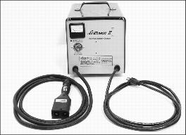
The battery charger is included with every E-GATOR Utility Vehicle. The charger is totally automatic and has no controls.
The charger monitors the battery set state of charge and contains an electronic timer that automatically turns the charger off as the batteries reach full charge.
The charger is a taper charge type which automatically decreases the rate of charge to provide good equalization of battery cells and reduce water usage.
Battery Charger Safety
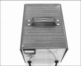
IMPORTANT: Avoid damage! Read and follow all safety warnings and operating instructions supplied with and inscribed on top of the charger. |
Charging Procedure
IMPORTANT: Avoid damage! An improper battery charging procedure may shorten battery life. Do not use battery additives, since the life of the batteries can be shortened. |
Become familiar with the operating instructions issued with the charger
Batteries are to be charged after each period of use.
Charging for short intervals when the vehicle is not being used is permissible.
In cold weather batteries should be taken off charge just prior to use.
Do not charge the batteries if the utility vehicle is not used that day.
Do not allow batteries to set in a state of discharge.
Prior to using the utility vehicle each day, always make sure the batteries are fully charged.
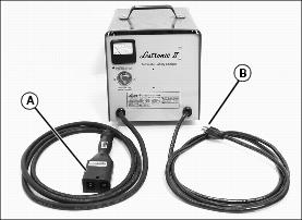
1. With the battery charger DC output cable plug (A) disconnected from the vehicle, connect the AC input plug (B) to a properly grounded outlet.
NOTE: The vehicle battery set can be charged with the service/drive switch in the SERVICE or DRIVE position.
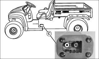
2. Connect the DC output cable plug to the battery receptacle (C) located below the operator seat on the left side of the vehicle.
NOTE: This utility vehicle is equipped with a charger interlock feature. Electrical current to the ignition is locked out when DC outlet plug is connected to the vehicle battery receptacle.
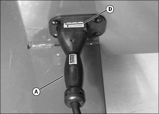
Grasp the DC output plug handle (A) and push the plug straight into the receptacle to the full engagement mark (D).
The charger will turn on with an audible "click" and "hum" after a short 3-10 second delay.
IMPORTANT: Avoid damage! Do not allow the battery charger to operate more then 30 minutes with the charge rate over 25 amperes. This operations will cause overheating and transformer burnout. |
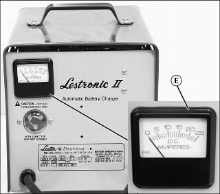
3. Monitor the ammeter (E) for the initial charge rate.
NOTE: If the batteries are heavily discharged, or the AC input line voltage is higher then nominal, the charge rate may exceed 25 amperes. Under normal conditions, the charge rate will taper to less then 25 amperes within 30 minutes.
The initial charge rate will vary between 16 and 25 amperes depending upon the state of battery discharge and AC line voltage.
The charge rate will decrease to 4-9 amperes for the last few hours of charge if all batteries are good.
The charger turns off automatically when the batteries reach full charge.
As batteries age, it is normal for the charge rate to increase above the 4 to 9 amp finish rate. The charger will still determine when the batteries are as charged as they can be and then turn off.
The required charge time varies with the depth of the discharge. Under normal conditions, the typical charge time is 10-12 hours. This is the normal charge time for batteries which have been discharged to 80% of their capacity.
As much as four additional hours may be required to properly charge the batteries under the following conditions:
Heavily discharged batteries (more than 80% discharged).
NOTE: When charging new or cold batteries, a higher then normal finishing charge voltage can be expected. This results in a low finish charge rate (2 - 5 amperes), and additional time is required to achieve equalization of all battery cells.
Charging new batteries (batteries with less than 20 to 50 discharge/charge cycles).
Charging optional larger batteries.
4. Disconnect the DC output cable plug from the vehicle receptacle.
Grasp the DC output plug handle (A) and pull the plug straight out of the receptacle.