
Operating
Daily Operating Checklist
o Remove grass and debris from engine compartment, muffler area, and front grille, before and after operating machine.
o Check area below machine for leaks.
o Check brakes and park brake operation.
o Inspect driveline CV boots for tears or punctures.
Avoid Damage to Plastic and Painted Surfaces
Do not wipe plastic parts unless rinsed first.
Insect repellent spray may damage plastic and painted surfaces. Do not spray insect repellent near machine.
Be careful not to spill brake fluid on machine components. Brake fluid may damage painted surfaces. Wipe up spilled brake fluid immediately.
Be careful not to spill fuel on machine. Fuel may damage surface. Wipe up spilled fuel immediately.
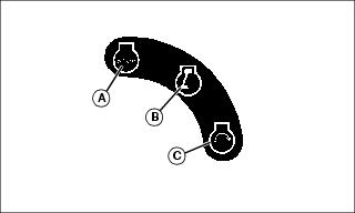
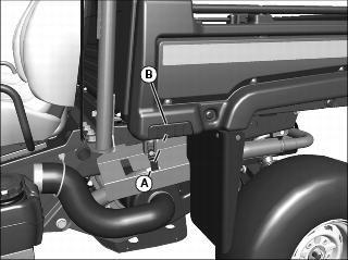
Using Hand Holds
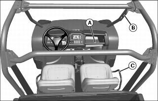
Hand holds are provided for passenger balance. When a passenger is present, they shall use two of the three hand holds at all times while the machine is moving. The dash bar (A), OPS handle (B), and side rail (C).
Adjusting Operator's Seat
1. Stop machine and move transaxle shift lever to N (neutral) position.
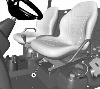
3. Push lever (A) to the left.
4. Slide seat forward or rearward to desired position.
Adjusting Passenger Seat
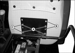
Picture Note: Front position shown.
2. Hold onto seat and remove cap screws (A).
3. Slide seat to the rearward (B) or forward (C) position.
4. Position bottom of seat against bracket and align correct holes with holes in seat.
5. Install original hardware to secure seat.
6. Tighten seat bracket hardware to 10 Nm (7.4 lb-ft)
Using Bench Seat
If a bench seat is installed, it is not adjustable.
See SERVICE MISCELLANEOUS for instructions to install and remove bench seat.
Using Seat Belt
NOTE: Shoulder harness is sensitive. An emergency lock device is built into the belt for your protection. To engage harness, pull harness slowly. Attempting to pull too fast or in a jerking motion will engage the locking mechanism and the harness will not release.
Periodically inspect seat belts for wear or damage. See Inspecting Seat Belt in SERVICE MISCELLANEOUS.
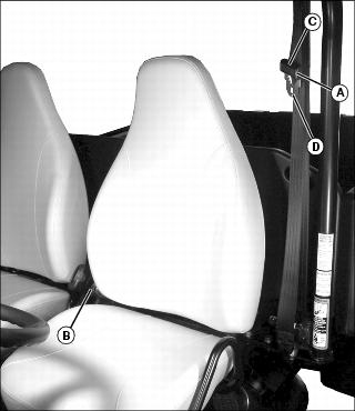
Fasten Belt
1. Grasp outer seat belt connector (A) from behind seat, pull out and across body to inner connector (B), at inside of seat.
2. To adjust outer connector for best fit, squeeze the upper (C) and lower (D) halves of outer connector together and adjust connector up or down along belt.
3. Push outer connector firmly into inner connector until it locks.
Release Belt
1. Press red button on inner connector to release seat belt.
Testing Safety Systems
The safety systems installed on your machine should be checked before each machine use. Be sure you have read the machine operator manual and are completely familiar with the operation of the machine before performing these safety system checks.
Use the following checkout procedures to check for normal operation of machine.
If there is a malfunction during one of these procedures, do not operate machine. See your authorized dealer for service.
Perform these tests in a clear open area. Keep bystanders away.
Testing the Safety Start System
1. Sit on the operator's seat.
2. Put key switch in OFF position.
4. Move transaxle shift lever forward to the high range position.
5. Turn key switch to start position. Engine should not crank. Turn key switch off.
6. Move transaxle shift lever to reverse position.
7. Turn key switch to start position. Engine should not crank. Turn key switch off.
Using Park Brake
NOTE: The park brake alarm will buzz if the machine is in gear and you try to move in forward or reverse before unlocking the park brake.
Always lock the park brake and remove the key before leaving the machine unattended. |
Locking the Park Brake:
1. Push down on brake pedal to hold machine in place.
2. Pull up on lever to engage park brake.
Unlocking the Park Brake:
1. Push down on brake pedal to hold machine in place.
3. Press center button on lever, and release lever down completely.
Using Travel Controls
2. Allow engine to come to a low idle speed.
NOTE: Always shift into low range when operating on wet or uneven terrain, or when towing or pushing heavy loads.
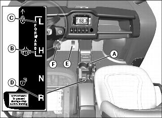
Forward - Push shift lever (A) forward to either high (B) or low (C) range.
Reverse - Push shift lever to left, then pull rearward to reverse (D) gear.
4. Look in the direction the vehicle will travel.
5. Push down accelerator pedal (E) slowly and smoothly to begin machine travel.
6. Release accelerator and apply brake pedal (F) evenly and firmly to slow down or stop.
Using Ignition Key Switch
Picture Note: Ignition key switch label.
A - STOP Position - With key in STOP position, all switched power is off, and engine should not run.
B - RUN Position - Turn key from STOP to this position and all switched power circuits will be on. If installed, electric power assist steering will activate.
C - START Position - Turn key to START position to crank the engine. Release key after engine has started and it will automatically return to the RUN position. The engine will continue to run.
Using Headlights
Ignition key switch must be in the RUN position to operate the lights. If the ignition key switch is in the RUN position and the engine is not running, the battery will discharge if the lights are allowed to remain on for an extended period of time.
Press top of light switch to turn headlights on.
NOTE: Be sure to turn lights off and turn the ignition key switch to STOP position, or lights will discharge battery.
Press bottom of light switch to turn headlights off.
Using Instrument Panel
Using Instrument Display
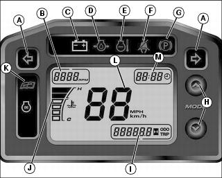
Using Instrument Display Arrow Keys
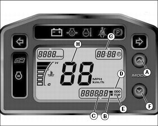
2. Push up arrow (A) to toggle between odometer, trip meter and hourmeter.
When "ODO" (D) is displayed, odometer indicator (C) will display the amount of miles or km the machine has moved. (To change between miles or km displayed, see next step.)
When "TRIP" (E) is displayed, the trip indicator (C) will display the amount of miles or km the machine has moved for a certain trip. (Press and hold the up arrow (A) for 5 seconds to change the display back to "0" for beginning a new trip.) (To change between miles or km displayed, see next step.)
When hourmeter (B) is illuminated, the indicator (C) will display the amount of hours the engine has run.
3. Push and hold up arrow (A) and down arrow (F) for approximately 3 seconds to obtain change clock display (G) and speed (H) screens.
NOTE: If you wait longer than 5 seconds before touching either the up or down arrow, the display will go back to the main screen and you will need to press and hold up and down arrows for 3 seconds again to get back to the clock display and speed screens.
Push up arrow (A) to change from 12 or 24 hour display.
Push down arrow (F) to obtain clock display screen that changes specific hour and minutes. Press up arrow to increase hour setting. Push down arrow (F) again to display minutes. Push up arrow to increase minute setting. (Press and hold up arrow for approximately 2 seconds to have minute counter run continuously. Release up button to stop minute counter.)
Push down arrow (F) to obtain speed display (H). Push up arrow to change from mph to km/h. This will change the speed display (H), and also when showing the odometer and trip displays.
Push down arrow again to exit display menu.
Using Accessory Outlet
NOTE: Accessory must be rated at 10 amps or less.
The accessory plug does not turn off with the key switch. Items connected to the accessory plug will continue to draw power, discharging the battery.
Remove 12-volt outlet cover and install accessory cord in outlet.
Install cover in outlet after use.
Using Turn Signal Switch (If Equipped)
NOTE: Turn signals will continue to flash when the ignition key switch is in the STOP position, discharging the battery.
Press at left end of turn signal switch to signal a left turn.
Press at right end of turn signal switch to signal a right turn.
Press at opposite end of turn signal switch until switch is centered to turn signal light off.
Using Hazard Lights (If Equipped)
NOTE: Hazard lights will continue to flash when the ignition key switch is in the STOP position, discharging the battery.
Press at top of hazard light switch to turn hazard lights on.
Press at bottom of hazard light switch to turn hazard lights off.
Using Front Blade Switch (If Equipped)
Press at top of front blade switch to raise blade.
Press at bottom of front blade switch to lower blade.
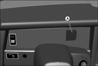
Using Storage Tray
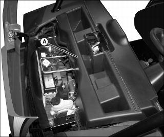
Storage tray (A) is located in front of machine under the hood.
1. Open hood to access the storage tray.
2. Secure all items to prevent damage from movement while operating the machine.
Starting the Engine
1. Sit on operator seat. Do not start engine at this time.
2. Push down on accelerator pedal to check free movement of pedal assembly. Release pedal.
NOTE: The machine has a neutral start safety switch. The engine will not start unless the transaxle shift lever is in N (Neutral) position.
3. Verify that transaxle shift lever is in N (Neutral) position.
4. Verify that park brake is locked.
5. Turn off headlights and accessories before starting vehicle.
6. Turn ignition key switch to the ON position.
7. Check that the following indicator lights are on:
Battery discharge light (on machines without power assist steering)
Glow plug/coolant temperature light for approximately 3 - 5 seconds
Battery discharge/steering malfunction light (on machines with power assist steering) should light briefly then go off indicating normal power steering function
8. When the glow plug/coolant temperature light turns off, turn ignition key switch to START position.
IMPORTANT: Avoid damage! Starter may be damaged if operated continuously for extended periods of time. Allow starter to cool down after several starting attempts. |
9. Release ignition key switch to the ON position when engine starts.
If engine does not start within five seconds, turn ignition key switch to OFF position and wait ten seconds before trying to start again.
In very cold conditions, attempt starting engine three times only, then wait 5 minutes before trying again. This will allow time for starter to cool and prevent damage to starter.
IMPORTANT: Avoid damage! Do not operate the engine at full throttle or under load until engine has warmed up, or engine damage could occur. |
10. Run engine at half speed for 2 or 3 minutes to warm the engine.
Stopping Engine
Always lock the park brake and remove the key before leaving the machine unattended. |
IMPORTANT: Avoid damage! Do not stop engine immediately after hard or extended operation. Keep engine running at low idle for about 2 minutes to prevent heat build-up. |
2. Move transaxle shift lever to N (Neutral) position.
4. Turn ignition key switch to OFF position.
Using Electric Power Assist Steering
The Battery Discharge/Steering Malfunction Light will indicate if there is a malfunction in power assist steering.
The light may go off and on during operation as an indicator that power assist steering has been reduced to protect the system. Full power assist steering is available when the vehicle is not moving. The level of assist is based on vehicle speed.
Normal steering operation has the electric power assist steering indicator light off. The indicator light flashes a single flash to indicate low battery voltage. If the indicator light remains on constantly or flashes continually during operation, contact your John Deere dealer.
Steering effort is adversely affected by low tire air pressure. Always keep tires at recommended air pressure.
Using Traction Assist
Traction assist provides better traction when rear wheels start to slip. Engaging the traction assist will cause both rear wheels to turn together at equal speed.
Engaging the Traction Assist:
IMPORTANT: Avoid damage! Incorrectly engaging traction assist may damage the transaxle. Reduce speed before engaging or disengaging traction assist. |
1. Stop or reduce engine speed to 1/3 throttle or less.
2. Pull traction assist lever up to the locked (vertical) position:
Traction assist will remain engaged as long as lever is up (vertical).
Disengaging the Traction Assist
NOTE: To ensure true disengagement of traction assist, you must equalize torque on both axles.
1. Stop or reduce engine speed to 1/3 throttle or less.
2. Drive the vehicle straight ahead at a constant speed.
3. Push lever down to unlocked position.
Using Four Wheel Drive
4WD On-Demand enables the front wheels to drive, but torque will not be applied until rear wheels begin to slip.
IMPORTANT: Avoid damage! Engaging 4WD On-Demand when the machine is stopped and the rear wheels are spinning will damage the gears. |
Push in on top of 2WD/4WD switch to enable the 4WD On-Demand system.
Push in on bottom of switch to disable the system.
Tips for operating 4WD On-Demand:
NOTE: Occasionally the 4WD On-Demand system will not disengage after a change in vehicle travel direction. This is known as "wedging." If this does occur, the vehicle will exhibit higher than usual steering efforts and driveline wind-up. To disengage (un-wedge) the system, reverse the direction of vehicle travel.
Maintain recommended front and rear tire pressures to ensure optimum performance on all surface conditions.
Disable 4WD On-Demand when driving machine on paved or hard packed surfaces to increase front tire life and reduce drive train wear.
Using the Cargo Box
Raising and Lowering with Manual Lift
1. Park the vehicle safely. (See Parking Safely in the SAFETY section.)
3. Disengage cargo box lock if installed.
4. Push down on cargo box to release pressure against latch (A).
5. Release latch by pulling latch towards grip (B) on cargo box. Allow lift cylinder to raise cargo box.
Raising and Lowering with Power Lift
1. Park the vehicle safely. (See Parking Safely in the SAFETY section.)
2. Disengage cargo box lock if installed.
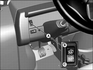
4. The cargo box switch (A) is located on the left side of the instrument panel.
5. Raise cargo box by pressing and holding top of rocker switch (B). Release switch when box is at desired dump height or when reaching maximum height.
NOTE: Allowing the pressure relief valve to open slightly (whine or squeal) after cargo box is fully lowered will help keep cargo box secure and reduce rattling caused by travel vibrations.
6. Completely lower cargo box by pressing and holding bottom of rocker switch (C).
Locking Box in Raised Position
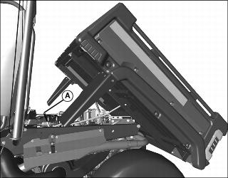
2. Pull down on the cargo box slightly and push rod (A) in toward center of box to locked position.
3. Check to be sure box is locked in raised position.
4. To lower cargo box, lift rod up and slowly push cargo box downward until it latches in fully lowered position.
Operating the Tailgate
Check condition of lanyards for wear or damage. Replace if cable is kinked or frayed. |
1. Check to be sure lanyards (A) are in place to support lowered tailgate.
2. Disconnect lanyards if you want to lower tailgate more than 90 degrees.
IMPORTANT: Avoid damage! Lower tailgate completely to unload cargo box only. Never drive with the tailgate hanging down. Tailgate can contact tires and cause damage. |
3. Pull back on handle (B) to unlock and lower tailgate.
4. Before raising tailgate, check for stones and debris caught in the gap between the tailgate and cargo box floor. To remove debris:
a. Lock the cargo box in raised position.
b. Rotate the tailgate slightly to free debris, and brush out the gap.
5. To raise tailgate, slowly push tailgate upward and lock into closed position.
6. Check to be sure tailgate is securely locked.
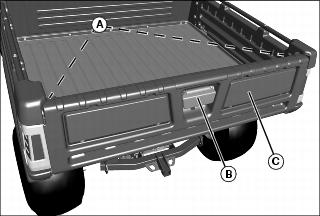
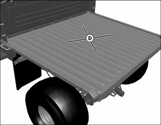
Using Cargo Box Tie Downs
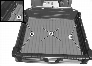
1. Arrange load so the weight is centered over the main cargo area (A).
2. Secure loads to the tie downs (B) in a safe and secure manner.
Removing the Tailgate
1. Check to be sure lanyards (A) are in place to support lowered tailgate.
2. Pull back on handle (B) to unlock and lower tailgate (C).
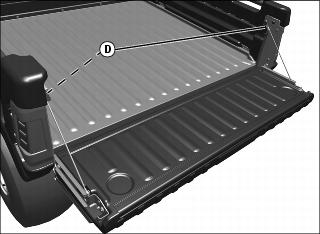
3. Loosen loop (D) on top of lanyards, disconnect from studs on cargo box side, and lower tailgate fully downward.
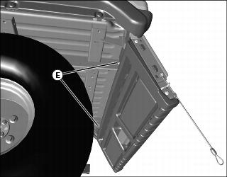
4. Loosen two nuts (E) on rear of floor panel, to allow side panels to be removed.
5. If equipped with taillights, disconnect the wiring harness and hang the harness in the rear of the box.
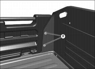
6. From behind driver's seat in cargo box, remove two nuts (F).
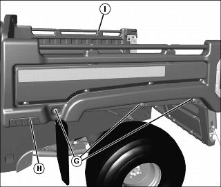
7. Loosen three bolts (G) in left side body panel (H). Do not completely remove bolts from clamp-on nuts.
8. Support the tailgate to avoid bushing damage. Move side body panel slightly outward and remove tailgate from left side body panel and right side body panel (I).
9. Install in reverse order of removal.
Operating in Flat Bed Mode
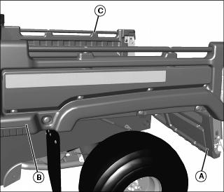
1. To operate machine in flat bed mode, remove tailgate (A) (See Removing the Tailgate).
2. Remove left (B) and right (C) side body panels.
3. Arrange load so the weight is centered over the main cargo area (D).
4. Install tailgate and side panels in reverse order of removal procedure (See Removing the Tailgate).
Determining Vehicle Load Capacity
Find weights and capacities for your machine model in SPECIFICATIONS.
Factors in Determining Vehicle Load Capacity
NOTE: Optional equipment or attachments that are not standard equipment, must be included when determining gross vehicle weight, and may reduce cargo box capacity.
b. Subtract the Gross Vehicle Weight (GVW) from the Gross Vehicle Weight Rating (GVWR).
c. The weight difference between the two numbers is the vehicle load capacity.
d. The Gross Vehicle Weight must be less than or equal to the Gross Vehicle Weight Rating. If GVW exceeds GVWR, remove excess weight from vehicle before operating.
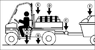
Example:
The example below is for an XUV diesel vehicle with, a 350 lb cargo load, a 200 lb operator, 220 lb of attachments and options (such as a heavy duty brush guard, OPS poly roof, cargo box power lift kit, etc), towing a trailer with 50 lb of tongue weight.
GVW = 2352 lb (200 + 1532 + 50 + 350 + 220)
Vehicle Load Capacity = GVWR (3120) less GVW (2352)
Vehicle Load Capacity = 768 lb
The remaining vehicle load capacity of 768 lb can be used to haul additional operator, passenger, cargo, cart tongue and attachment weight.
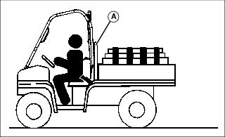
Loading the Cargo Box
See capacities in SPECIFICATIONS.
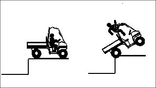
Reduce load by half when operating over rough, hilly, or steep terrain. Do not overload vehicle. Limit loads to those that can be safely controlled.
Reduce speed and exercise extreme caution when operating over rough, hilly, or steep terrain.
Securely anchor and evenly distribute loads in cargo box, when loading objects into vehicle. Shifting loads will affect stability.
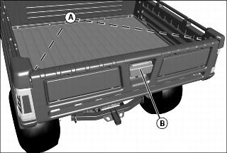
Do not load above load guard (A).
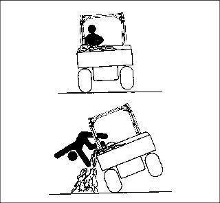
Avoid concentrated loads at rear or side of cargo box to prevent vehicle from tipping over. Be sure load is evenly distributed.
Because there is a big difference in weight between dry and wet sand, the only way of getting true weight of the load you are carrying is by using a scale.
Printed weight is normally on bagged and other material.
Box Volume Capacity
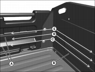
Use rub rails (A) in left and right side panels, and form beads (B) in cargo box front panel to determine cargo box volume.
101 cm (4 in.) load height (C) = 150 L (5.3 cu ft).
152 cm (6 in.) load height (D) = 226 L (8 cu ft).
203 cm (8 in.) load height (E) = 303 L (10.7 cu ft).
NOTE: Use table below to determine height of common cargo box materials.
Do not exceed Gross Vehicle Weight (GVW).
Emptying Cargo Box
1. Back up vehicle to dump site.
2. Park the vehicle safely. (See Parking Safely in the SAFETY section.)
IMPORTANT: Avoid damage! Stop emptying immediately if overload pressure relief valve opens. Lower cargo box completely and remove excess load by hand before dumping. |
4. Raise cargo box to dump load.
5. Lower cargo box when empty.
6. Close tailgate. Do not drive vehicle with cargo box in raised position.
Towing Loads
To provide adequate braking ability and traction, weight of towed load (trailer plus cargo) must never exceed the vehicle payload (operator plus passenger plus cargo box load).
When operating over rough, hilly, or steep terrain and reducing cargo load by half, any towed load should also be reduced accordingly.
Do not tow a load that exceeds towing capacity listed in SPECIFICATIONS.
Do not exceed cart tongue weight listed in SPECIFICATIONS. (The tongue load of a trailer should be approximately 10% of the total trailer weight.)
Tow load at a speed slow enough to maintain control.
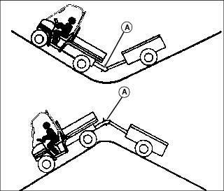
Always use approved hitch and hitch point provided for the utility vehicle. Do NOT modify the hitch or hitch point in any way.
Using Correct Tires and Inflation
See tire descriptions and inflation pressures for load conditions in SPECIFICATIONS.
Tires
Use of John Deere approved original equipment or optional equipment is recommended. To ensure maximum machine performance and ride quality, do not mix size, type, or placement of tires. Failure to place tires per the guidelines could result in reduced machine performance, diminished traction and poor handling.
Inflation
IMPORTANT: Avoid damage! Over inflation may damage tires and diminish ride quality. Under inflation could cause wheel damage when riding over rough terrain. |
An accurate low pressure gauge is available at your John Deere dealer.
Tire Chains
Transporting Machine
Towing the Machine
Unlock park brake and keep machine transaxle shift lever in neutral (N) position for towing.
Machine Tie Down Locations
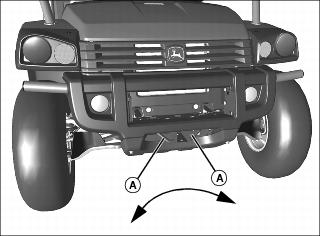
Picture Note: Fasten front of machine through tie down points (A) on front of machine to trailer with a heavy-duty strap, chain, or cable. Strap must be directed down and outward from machine.
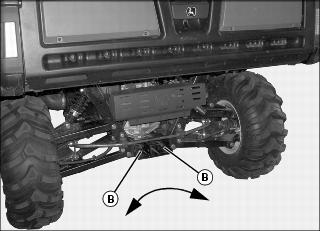
Picture Note: Fasten rear of machine through tie down points (B) on rear of machine to trailer with a heavy-duty strap, chain, or cable. Strap must be directed down and outward from machine.
Hauling the Machine
NOTE: Space limitations may vary from one truck manufacturer to another. Short bed trucks do not have the necessary length requirement to accommodate the machine.
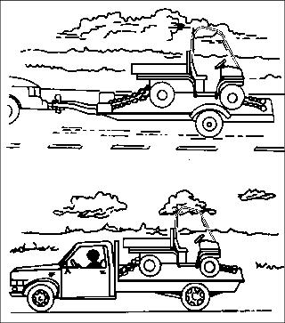
1. Back machine onto the trailer or truck.
2. Leave transaxle shift lever in forward or reverse gear.
3. Park machine safely. (See Parking Safely in the SAFETY section.)
4. Fasten machine to trailer or truck with straps, chains, or cables.
5. Equip the trailer or truck with all the necessary lights and signs required by local, state, provincial, or federal laws.