
Service Transmission
Transaxle Oil
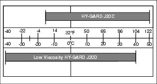
Use the appropriate oil viscosity based on these air temperature ranges. Operating outside of these recommended oil air temperature ranges may cause premature hydrostatic transmission or hydraulic system failures.
John Deere J20C HY-GARD™ transmission and hydraulic oil is recommended. John Deere J20D Low Viscosity HY-GARD™ transmission and hydraulic oil may be used, if within the specified temperature range.
Other oils may be used if above recommended John Deere oils are not available, provided they meet one of the following specifications:
• John Deere Standard JDM J20C;
• John Deere Standard JDM J20D.
Cleaning Hydraulic Oil Cooler
• Clear work area of bystanders. • Wear eye protection when using compressed air for cleaning purposes. |
IMPORTANT: Avoid damage! To ensure proper cooling, keep the cooling fins clean at all times. Operating the machine with obstructed cooling fins could cause damage due to overheating. |
1. Park machine safely. (See Parking Safely in the Safety section.)
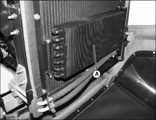
3. Clean hydraulic cooler(A) with a rag, brush, or compressed air.
Checking Hydraulic Oil Level
IMPORTANT: Avoid damage! Hot hydraulic oil will expand and show incorrect oil level. Check reservoir tank: |
1. Park machine safely. (See Parking Safely in the Safety section.)

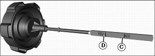
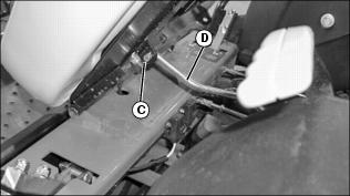
5. Oil level should be between minimum (C) and maximum indicators (D).
Changing Hydraulic Oil and Filter
1. Park machine safely. (Refer to Parking Safely in the Safety section.)
2. Allow engine and hydraulic oil reservoir to cool.
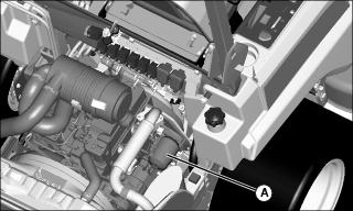
Picture Note: Parts have been removed for photo clarity.
4. Put a container under hydraulic oil filter (A).
5. Turn hydraulic oil filter four turns counterclockwise to drain oil from tank.
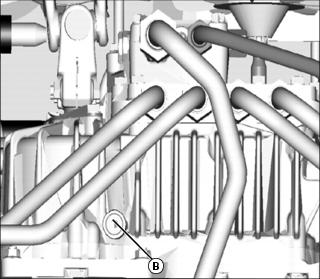
Picture Note: Bottom of hydraulic pump shown
6. Put a container under drain plug (B).
9. Apply a film of clean oil on gasket of new filter.
10. Install filter. Turn filter clockwise until gasket makes contact with the mounting surface. Tighten 1/2 to 3/4 turn after gasket contact.
12. Clean area around reservoir fill cap (C).
14. Fill oil reservoir with approximately 22.8L (6 gal) of oil.
17. Move throttle lever to the slow position.
18. Run machine in idle position for 3 minutes.
20. Cycle motion control levers forward and rearward several times. Check for leaks around filter.
21. Stop the engine. Check oil level. Add oil if necessary.
Checking and Adjusting Motion Control Linkages
Checking Motion Control Linkages
NOTE: Check and adjust motion control linkages with the machine parked on a hard, level surface.
1. Sit on operator’s seat and place both motion control levers in the neutral lock position.
3. Set throttle lever to the fast position.
5. If the drive wheels begin to creep, an adjustment is required.
Adjusting Motion Control Linkages
1. Stop engine and lock park brake.
2. Lift drive wheels off the ground using a safe lifting device and use jackstands to support machine.
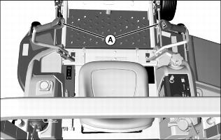
3. Move both motion control levers (A) to the neutral lock position.
4. Adjust seat fully rearward.
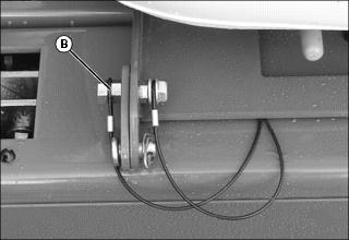
5. Remove tethered lock bolt and nut (B) from front of seat frame.
6. Lift and secure operator seat in the raised position.
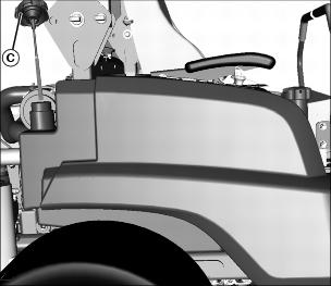
7. Remove cotter pin and washer (C) from support rod (D) and remove seat rod from side of seat frame.
8. Tilt seat forward to rest on front frame.
9. Raise rear of machine with a safe lifting device.
• Support rear of machine with wood blocks or jackstands.
• Rear drive wheels must have the ability to rotate freely.
10. Activate operator seat safety switch:
NOTE: To avoid damaging the seat cushion, cover end of wood block with a rag.
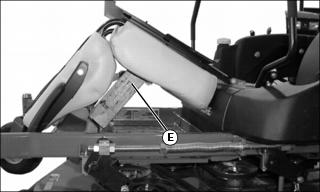
• Place a wooden block (E) approximately 33-38 cm (13-14 in.) long between the foot plate and the center of the seat.
12. Set throttle to the fast position.
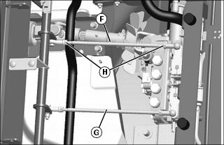
14. Locate right (F) and left (G) and motion control linkages.
15. Be sure the right motion control lever is in the neutral lock position.
• The right drive wheel must not turn. If it does turn, adjust the right motion control linkage (F):
a. Loosen the hex nuts (H) on each end of the right link.
b. Adjust the link until the right wheel stops rotating completely.
16. Move the right motion control lever completely forward and rearward in the slot and then back to the neutral lock position.
• The right drive wheel must stop completely. If the drive wheel does not completely stop rotating, repeat step 14 and 15.
17. Repeat procedure to adjust the left motion control linkage (G).
19. Move both motion control levers to the neutral lock position.
20. Remove wood block (E) from between foot plate and the operator seat.
22. Install support rod (D) to side of seat frame and secure with washer and cotter pin (C).
24. Install tethered lock bolt and nut (B) from front of seat frame.