
Service Steering & Brakes
Adjusting Front Caster Spindle Bearing
NOTE: Adjustment required only if front caster wheel vibrates during travel.
1. Park machine safely. (Refer to Parking Safely in the Safety section.)
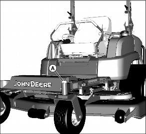
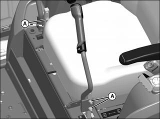
2. Remove dust cover (A) from top of spindle.
4. Turn castle nut 1/4 turn clockwise.
5. Replace cotter pin. Do not loosen the castlenut to align cotter pin hole, increase the tightening to align.
7. Test machine to determine if vibration is still present. Repeat adjustment as necessary.
Checking and Aligning Motion Control Levers
Check Alignment
1. Park machine safely. (Refer to Parking Safely in the SAFETY section.)
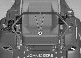
2. Move both motion control levers inward in the neutral position.
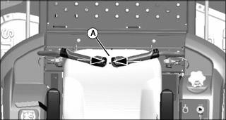
3. Check gap (A) between the levers. The recommended gap is 6 -19 mm (1/4-3/4 in.). Adjust if gap is outside recommendation.
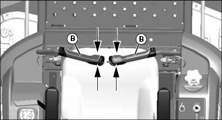
4. If the horizontal position of the control levers (B) are not equal, an adjustment is necessary.
Adjusting Lever Gap
1. Put the levers in neutral position.
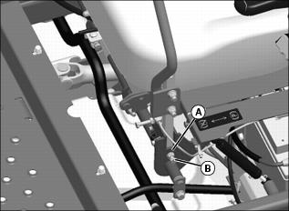
Picture Note: Parts have been removed for photo clarity.
2. Loosen jam nut (A).Turn set screw (B):
• Clockwise to move lever outward
• Counterclockwise to move lever inward
NOTE: Adjust levers alternating from side to side.
Adjusting Lever Horizontal Alignment
1. Adjust position of motion control levers:
• Pivot both levers forward or rearward until levers are aligned.
Adjusting Lever Height
The levers have two height adjustment positions. To change position:

1. Loosen and remove the bolts and nuts (A) securing the levers to the linkage.
2. Align the levers with the second of holes in the linkage.
3. Install the bolts and nuts and tighten securely.
Checking and Adjusting Motion Control Levers Gap
Checking Alignment
1. Park machine safely. (See Parking Safely in the SAFETY section.)
2. Move motion control levers (A) inward to neutral position.
3. If the ends of the levers strike against each other while in the neutral position an adjustment is needed.
Adjustment Procedure
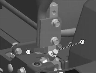
2. Tighten left and right adjustment bolts (C) slightly to increase gap between handles. The recommended gap between handles is 5-10 mm (0.2-0.4 in.)
3. Tighten jam nuts to hold adjustment bolts in place.
Adjusting Park Brake
1. Park machine safely. (Refer to Parking Safely in the Safety section.)
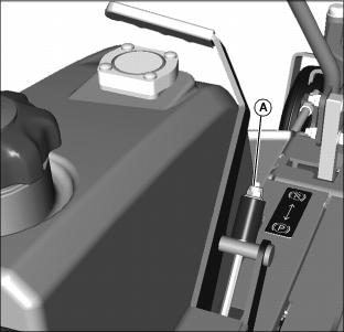
Picture Note: Picture Note: Seat removed for photo clarity.
2. Turn nut (A) clockwise to tighten, or counter clockwise to loosen park brake setting.