Service Electrical
Battery Warning
WARNING: Battery posts, terminals and related accessories contain lead and lead components, chemicals known to the State of California to cause cancer and reproductive harm. Wash hands after handling.
Service the Battery Safely
 c CAUTION: Avoid injury! The battery produces a flammable and explosive gas. The battery may explode:
• Do not smoke or have open flame near battery.
• Wear eye protection and gloves.
• Do not allow direct metal contact across battery posts.
• Remove negative cable first when disconnecting.
• Install negative cable last when connecting.
|
Checking the Battery (Sealed Batteries)
NOTE: Do not attempt to open, add fluid or service battery. Any attempt to do so will void warranty.
• Keep battery and terminals clean.
• Keep battery bolts tight.
• Keep small vent holes open.
IMPORTANT: Avoid damage! This battery comes fully charged. If the machine is not used by the service expiration date indicated on the battery, charge the battery.
|
• Recharge, if necessary, at 6-10 amperes for 1 hour.
Cleaning Battery and Terminals
1. Park machine safely. (See Parking Safely in the SAFETY section.)
2. Disconnect and remove battery.
3. Wash battery with solution of four tablespoons of baking soda to one gallon of water. Be careful not to get the soda solution into the cells.
4. Rinse the battery with plain water and dry.
5. Clean terminals and battery cable ends with wire brush until bright.
6. Install battery.
7. Attach cables to battery terminals, beginning with the positive cable, using washers and nuts.
8. Apply spray lubricant to terminal to prevent corrosion.
Using Booster Battery
|
c CAUTION: Avoid injury! The battery produces a flammable and explosive gas. The battery may explode:
• Do not smoke or have open flame near battery.
• Wear eye protection and gloves.
• Do not jump start or charge a frozen battery. Warm battery to 16?C (60?F).
• Do not connect the negative (-) booster cable to the negative (-) terminal of the discharged battery. Connect at a good ground location away from the discharged battery.
|
M71044
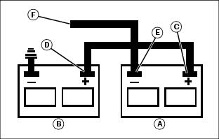
A - Booster Battery
B - Disabled Vehicle Battery
1. Connect positive (+) booster cable to booster battery (A) positive (+) post (C).
2. Connect the other end of positive (+) booster cable to the disabled vehicle battery (B) positive (+) post (D).
3. Connect negative (–) booster cable to booster battery negative (–) post (E).
IMPORTANT: Avoid damage! Electric charge from booster battery can damage machine components. Do not install negative booster cable to machine frame. Install only to the engine block.
Install negative booster cable away from moving parts in the engine compartment, such as belts and fan blades.
|
4. Connect the other end (F) of negative (–) booster cable to a metal part of the disabled machine engine block away from battery.
5. Start the engine of the disabled machine and run machine for several minutes.
6. Carefully disconnect the booster cables in the exact reverse order: negative cable first and then the positive cable.
Replacing Fuses and Relays
IMPORTANT: Avoid damage! Help prevent machine circuit damage. Make sure replacement fuse is the correct size.
|
1. Open hood.
MX44478
MX44479
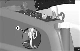
Picture Note: Diode pack located under console cover.
2. Locate and replace defective fuses or relays.
• Remove relay, fuse block or diode pack.
• Push in relay, fuse block or diode pack.
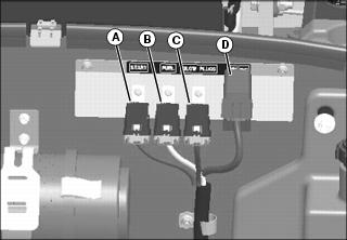
Relays, Fuse and Diode Block, Diode Pack Identification
• A = Start Relay
• B = Fuel Solenoid Relay
• C = Glow Plug Relay
• D = Fuse and Diode Block
• E = Diode Pack
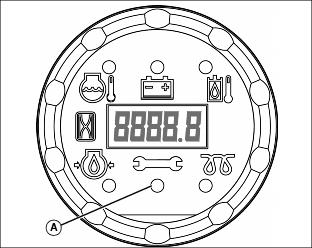
Diagnostic Light Check
The electronic control module provides a diagnostic light to help the operator identify operational and electrical problems by flashing a diagnostic code.
Diagnostic “Real Time” Codes
1. Park machine safely. (See Park Safely in SAFETY section.)
NOTE: The operator can be seated on the machine or standing next to the machine.
2. Turn the key to the START position and release key to RUN mode.
MX44361
TCU27896
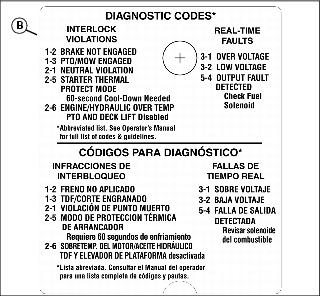
Picture Note: Diagnostic code label is located on right side console beside operator’s seat.
3. If starter does not engage, use the diagnostic light (A) and diagnostic codes (B) to diagnose the problem.
• BRAKE NOT ENGAGED (1-2) diagnostic code: one flash, a short pause and two additional flashes. This code sequence indicates that the park brake switch has not been activated during an attempted engine start or while the engine is idled with the operator out of the seat. Lock park brake to start engine or leave operator seat with the engine at idle.
• NEUTRAL VIOLATION (2-1) diagnostic code: two flashes, a short pause and one additional flash. This code sequence indicates motion control levers are not in the NEUTRAL position during an attempted start. Place both motion control levers in the neutral position before attempting to start.
This code will also flash if the park brake is applied with the motion control levers out of the neutral position. The engine will stop.
• CRANK TIME EXCEEDED (2-4) diagnostic code: two flashes, a short pause and four additional flashes. This code sequence indicates the starter has been engaged for 20 seconds and then disengaged by the control module. Turn the switch to the OFF position and begin another start sequence.
• STARTER THERMAL PROTECT MODE (2-5) diagnostic code: two flashes, a short pause and five additional flashes. This code sequence indicates that the control module has started a 60-second cool-down period to prevent the starter from overheating. Turn key switch to OFF position and let the starter cool down for at least 60 seconds before making another attempt to start engine.
• ENGINE/HYDRAULIC OVER TEMP (2-6) diagnostic code: two flashes, a short pause and six additional flashes. This code sequence indicates that the engine coolant or hydraulic oil has exceeded the high temperature limit. Turn key switch to OFF position and let the machine cool down before further operation.
4. Once the unit has started and/or while operating the machine, the following codes may occur:
NOTE: For safety, the PTO will not engage with the park brake locked and/or operator out of seat.
• PTO/MOW ENGAGED (1-3) diagnostic code: one flash, a short pause and three additional flashes. This code sequence Indicates that there was an attempted start with the PTO turned on. Turn PTO switch OFF before attempting to start.
This code will also flash if the machine and PTO are running with the brake released and the operator leaves the seat. The engine and PTO will stop Turn PTO switch OFF.
• OVER VOLTAGE (3-1) diagnostic code: three flashes, a short pause and one additional flash. This code sequence indicates that the electronic control unit has detected a voltage higher than normal in the electrical system. If the problem is severe, the control unit may disable the PTO output to the PTO clutch. Check electrical wiring for loose connections, specifically the battery positive and negative, starter, and frame ground on engine block.
• LOW VOLTAGE (3-2) diagnostic code: three flashes, a short pause and two additional flashes. This code sequence indicates that the electrical system voltage has dropped below9 volts and the charging system is not functioning. This code will not display as the engine is being started, as it is normal for system voltage to drop below 9 volts during cranking.
5. Refer to the troubleshooting section for additional diagnostic codes. If further diagnostic assistance is needed, refer to the Technical Manual or consult your John Deere distributor.
Diagnostic Test Mode
This is a troubleshooting mode that can be used to check the integrity of the switches, sensors, wiring, and hardware of the control module. The diagnostic information is generated in the control module and displayed through the the diagnostic indicator on the display module. Please refer to the troubleshooting section of this manual for more information.
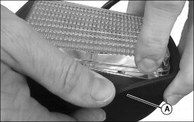
Replacing Light Bulb
Removing
|
c CAUTION: Avoid injury! Halogen light bulb contains gas under pressure. The bulb may shatter if the glass is scratched or dropped. Wear eye protection and handle bulb with care when replacing.
|
IMPORTANT: Avoid damage! Do not touch glass headlight bulb with bare skin or bulb may fail prematurely. Use gloves or a cloth when inspecting or replacing the bulb.
|
DM2069
1. Remove rubber cover (A).
DM2070
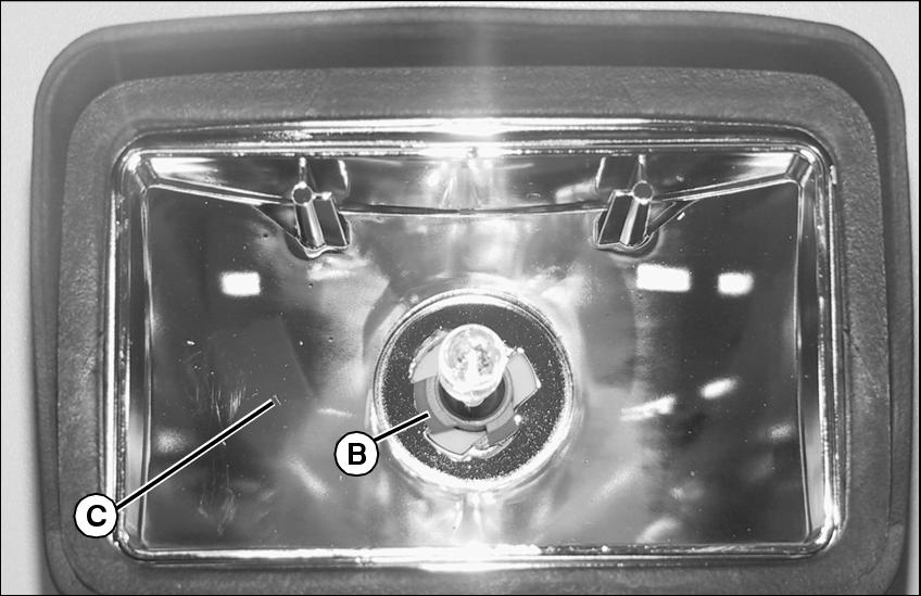
2. Rotate bulb fitting (B) and remove from lamp unit (C).
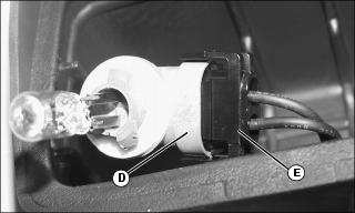
DM2071
3. Separate fitting (D) from plug (E).
Installing
Installing is the opposite of removing light bulb.
|