
Preparing Vehicle
Verify Frame Member Reinforcement
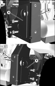
The assembly section of this manual refers to the removal and installation of side plates (A) and reinforced frame members (B).
Determine if mower is equipped with reinforced frame members. If not, parts (TCA19292 and TCA19293) must be ordered and installed on mower prior to installing MCS.
• Reinforced frame members and side plates are not necessary on ZTrak Estate series.
• Reinforced frame members are factory installed on ZTrak Pro series models listed below. Removal of frame members and installation of side plates is not necessary.
• Z810A through Z850A - serial numbers 020001 and above.
• Confirm that mower is equipped with reinforced frame members by measuring material thickness:
• Reinforced frame members are 4.55 mm (3/16 in.) thick.
• Non-reinforced frame members are 3.42 mm (1/8 in.) thick.
Checking Tire Pressure
Check tire pressure of machine before installing hopper. See your machine operator’s manual.
Installing Proper Mower Blades
For maximum performance from your material collection system (MCS), install the correct mower blades for your application:
• Mulching Blades - Not for use with MCS.
• Standard Blades - Standard blades are designed for bagging, side discharging, and all mowing conditions.
Installing Mounting Bracket for MCS Blower
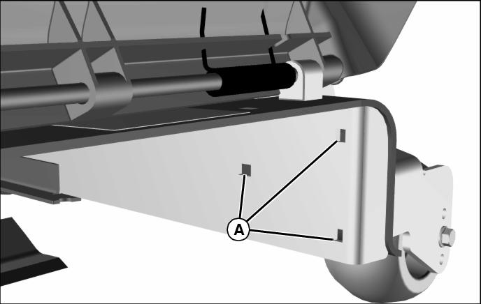
1. Lift discharge chute up and locate mounting holes (A) for front bracket.
Picture Note: Hardware removed for clarity. Position bracket as shown with blower pivot tube toward bottom.
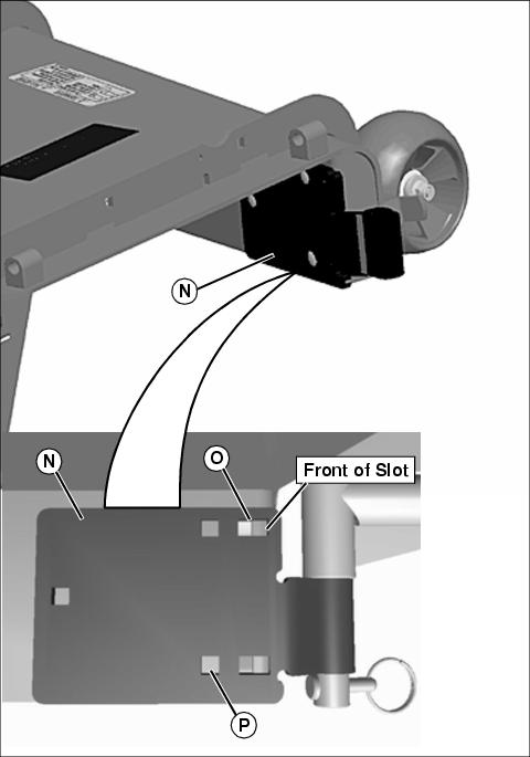
2. Position front pivot bracket (N) flush with deck.
3. Install and tighten three M8 X 25 carriage bolts and locknuts in locations listed below:
• 48 in deck located in back of slot (O)
• 54 in deck located in the middle of slot (O)
• 60 in. deck is located front of slot (O).
• 72 in. deck is location (P).
Bracket Assembly for all Mulch on Demand Decks.
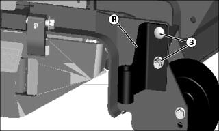
1. Position front pivot bracket (R) flush with outside scalp wheel frame.
2. Install and two M8 X 25 carriage bolts (S) and locknuts, and secure bracket into place.
Install Blower Support Bracket
Picture Note: Z800/Z900 Series shown
1. Remove screws and rear right anti scalp wheel assembly (A) from mower deck.
2. Position blower support bracket (B) in place flush against deck.
3. install anti scalp wheel onto bracket and secure in place with new provided M8x30 screws (C).
Install Pulley and Spacer
1. Remove belt shield on discharge chute side of mower deck.

2. Install five spacers (A) and extra pulley (B) on sheave (C) using four M8x50 flange head bolts (D), and tighten to 24 N•m (18 lb-ft).
Install New Gate (Mulch on Demand Mower Decks Only)
1. Park machine safely. (See Parking Safely in the SAFETY section.)
5. Install new gate (C) and attach link assembly.
Gate Extension for MCS Gate
NOTE: Gate extension must be installed if machine is operated without MCS blower.
1. Install gate extension (D) with hardware and secure in place.
Install Mulch-On-Demand Position Lever (Mulch on Demand Mower Decks Only)
1. Park machine safely. (See Parking Safely in the SAFETY section.)
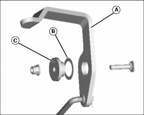
2. Place shim washer (B) onto Insert bushing (C).
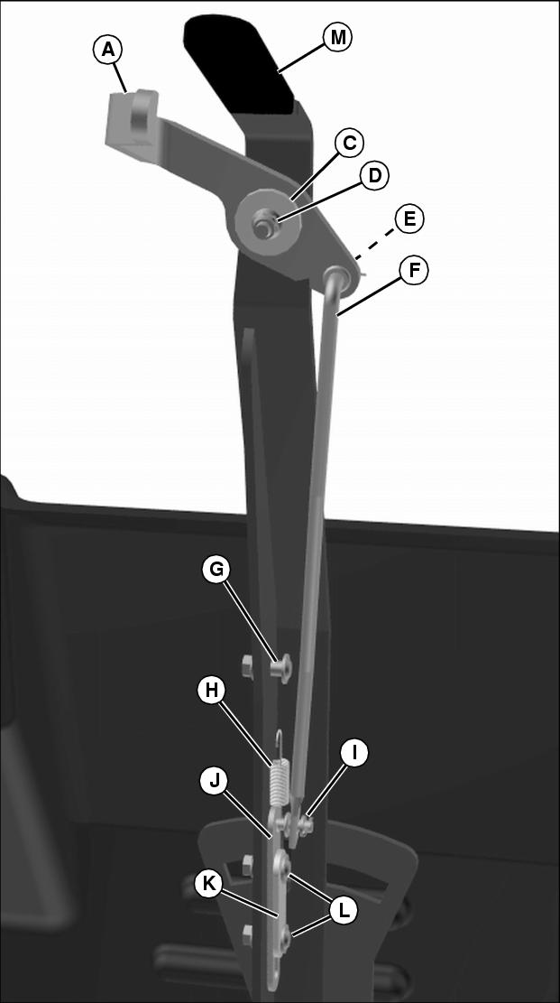
3. Insert bushing (C) into lever release (A) and attach to deck mode lever (M) with M6x30 cap screw and nut (D). Tighten hardware.
4. Position pawl plate (J) and shim latch (K) in place and secure with two M6x21 socket head shoulder bolts and nuts (L). Do not overtighten hardware.
5. Install M6x21 socket head shoulder bolt and nut (G). Tighten hardware.
6. Install tension spring (H) from pawl plate (J) to socket head shoulder bolt (G).
7. Install link latch (F) to lever release and pawl plate. Secure link latch with M8.4x1.6 washer and cotter pin (E) and M6.4x1.6 washer and cotter pin (I). Spread cotter pins to secure in place.
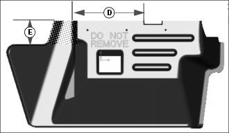
Trim Discharge Chute
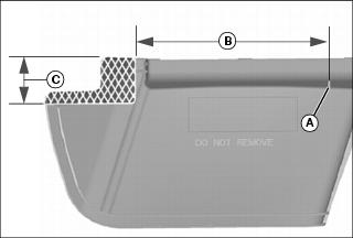
1. Begin at point (A) and measure distance (B) as shown. Scribe a mark.
2. Measure distance (C) beginning from hinge side of guard as shown. Scribe a mark.
3. Extend lines from both marks so they meet at a 90? angle and identify the shaded area as shown.
4. Remove shaded area using a suitable cutting tool.
Specifications
Specifications (For Mulch on Demand Decks)
Installing Weight Bracket
Parts in Kit (Weight Bracket)
NOTE: Secure and support vehicle as required. Take all safety precautions.
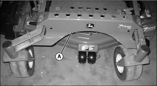
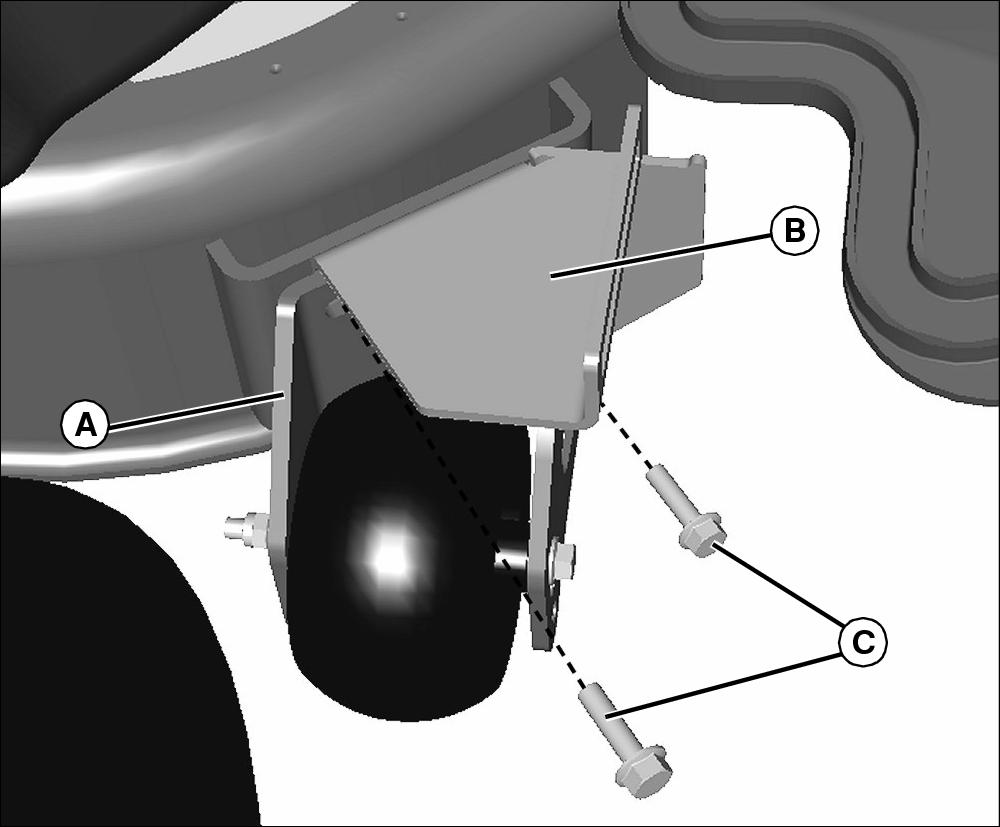
2. Clean front cross member (A) area of any debris.
3. Center weight bracket on cross member.
Picture Note: Front caster wheel not shown for photo clarity only.
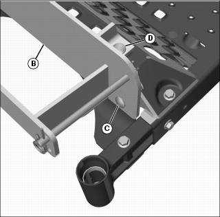
4. Align front mounting holes of the weight bracket (B) with the holes in the cross member.
5. Install M12x35 carriage bolts (C) and nuts. Tighten all hardware.
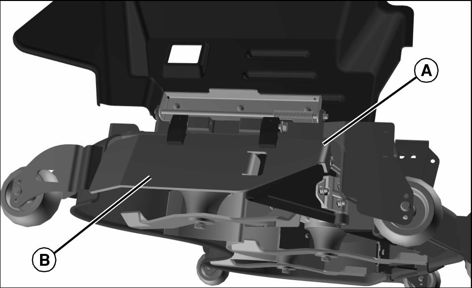
6. Install M12x50 carriage bolts (D) through top of weight bracket.
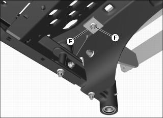
7. Install backing plates (E) and nuts (F). Tighten all hardware.