
Assembly
Dump From Seat Hopper Parts List
Blower Assembly Parts List
Assemble Blower
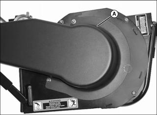
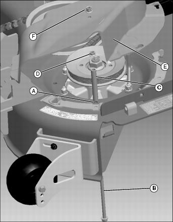
1. Remove belt guard (A) and secondary drive belt (B).
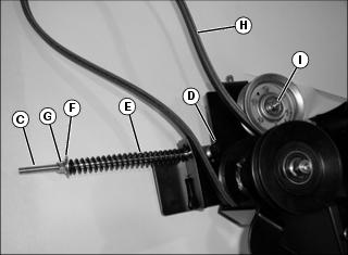
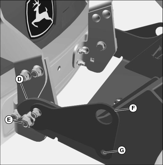
2. Install primary tension rod (C), retaining clip (D), spring (E), washer (F), and locknut (G).
3. Install primary drive belt (H).
4. Tighten hardware on idler pulley (I).
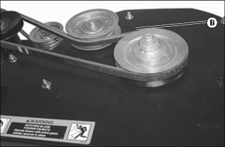
5. Install secondary drive belt (B) and tighten idler pulley.
6. Adjust secondary drive belt.
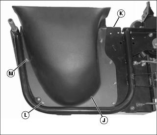
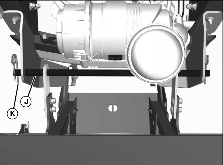
Picture Note: Deck boot for 48/54 in. shown. Socket head cap screw (M) must be installed in this location.
8. Install blower boot (J) on the bottom of blower housing (K) using the appropriate quantity of M6x20 square neck bolts (L) and one M6x20 socket head bolt (M) with M6 locknuts.
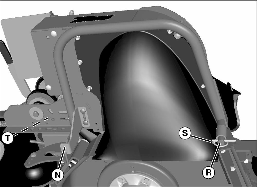
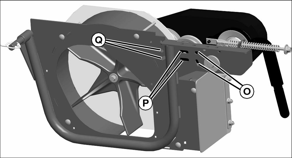
9. Install rear mounting bracket (N) using two M8x25 carriage bolt and locknuts:
• For 72 in. decks, place bracket into slots (O).
• For 60 in. and all Mulch on Demand decks, place bracket into slots (P).
• For 48 and 54 in. decks place bracket into slots (Q).
10. Install blower front pivot pin (R) and secure with lynch pin (S) in front mounting bracket. Swing blower into position, and align rear mounting bracket to install release handle (T) and M8x25 carriage bolt.
11. Tighten hardware on rear mounting bracket.
12. Connect primary drive belt from blower to drive sheave on deck.
13. Install primary belt guard onto deck.
14. Adjust primary drive belt.
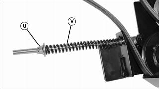
15. Tighten nut (U) on tension rod until spring (V) length is 150 +/- 10 mm (6.0 +/- 0.4 in.).
Assembling Frame
1. Park machine safely. (See Parking Safely in the SAFETY section.)
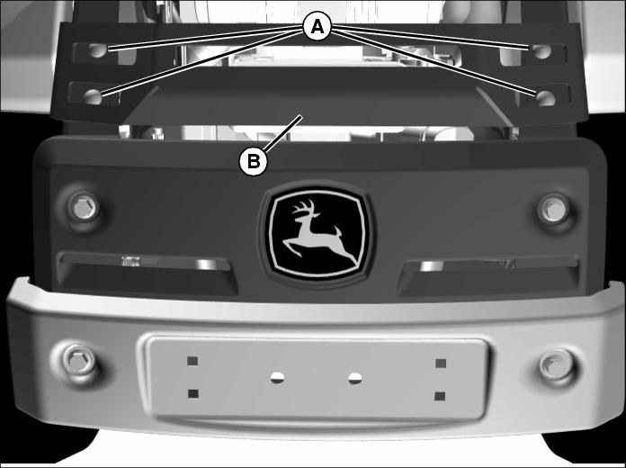
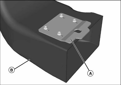
2. If model is equipped with an engine guard, remove four carriage bolts, washers, and locknuts (A), and remove engine guard (B).
NOTE: If installed, remove rear side weights from mower. They are not compatible with an MCS.
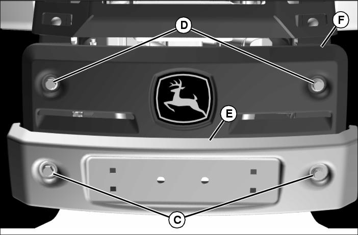
3. Remove two M12 nuts (C) and two M12x30 flange head bolts (D). Remove bumper (E) and rear grille (F).
NOTE: Refer to Verify Frame Member Reinforcement in Preparing Vehicle section to determine if the following two steps are necessary.

4. Remove three M12x30 flange head bolts on each side holding the rear frame members (G). Remove frame members and replace with reinforced frame members provided. Tighten frame flange head bolts to 115-122 N•m (85-90 lb-ft).
5. Install left plate (H) and right plate (I) with three M12x30 flange head bolts and locknuts (J) on each side.
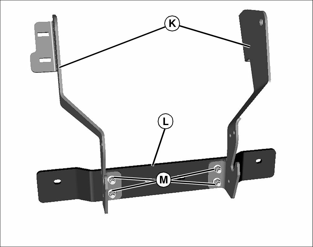
6. Install two side brackets (K) to the steel bumper (L) with four M10 flange head bolts (M) and locknuts. Leave slightly loose until tops of brackets are secure in place.
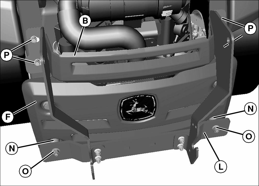
7. Install rear grille (F) using existing hardware.
8. Install steel bumper (L) to machine using spacers (N), M12x70 bolts, and M12 locknuts (O). Tighten locknuts to 115 N•m (85 lb-ft).
NOTE: On models with an engine guard (B), be certain to install before securing top of brackets to machine.
9. Secure tops of brackets with four M10x30 flange head bolts, washers, and locknuts (P) in the mounting location for the engine guard. Tighten all bracket hardware.

10. Install plate (Q) to side brackets using three M10x30 carriage bolts and locknuts (R). Do not tighten hardware at this time. Repeat for other side.
11. Install M12x60 hex head bolt (S), bushing (T) and locknut (U). Tighten all hardware securely.
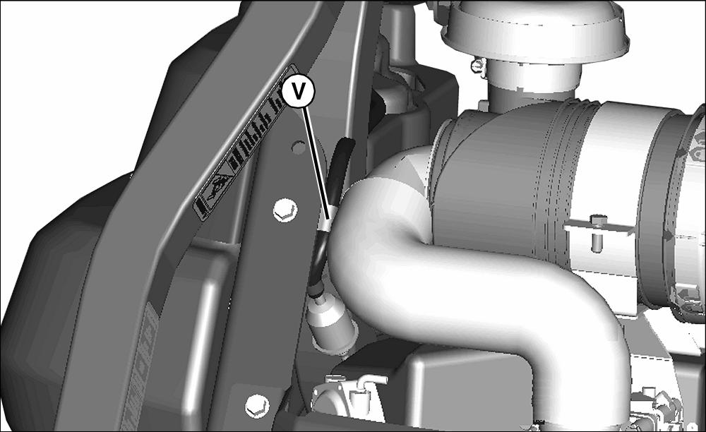
NOTE: On some models, there is a fuel line clamp (V) located at one of the holes needed for mounting one of the reinforcement plates. Be certain to install fuel line clamp as shown.
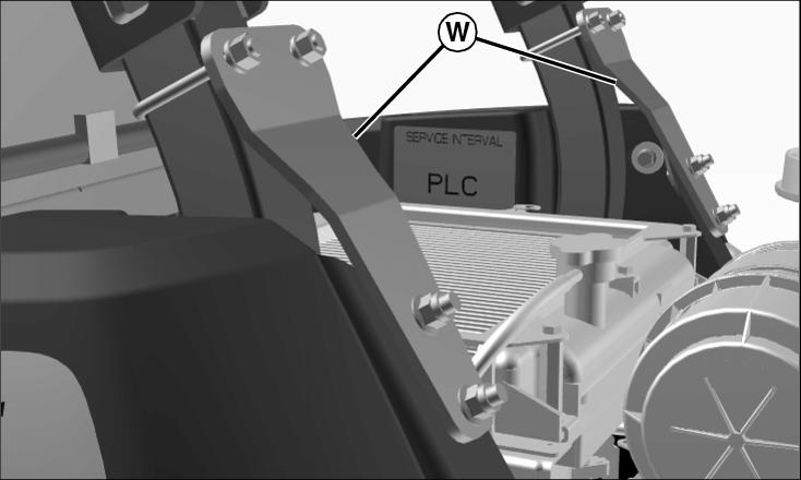
12. Install reinforcement plates (W) with U-bolts and supporting hardware.
Installing Hopper Assembly
1. Park machine safely. (See Parking Safely in the SAFETY section.)
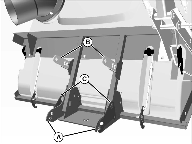
2. Position hopper assembly behind the machine. Make sure frame arms (A) are aligned with hopper mounting hardware at rear frame of machine.
3. Install upper latches (B) with four M10x25 carriage bolts and locknuts. Leave hardware loose.
4. Lift open latch levers (C).
5. Place frame arms (D) around hopper mounting pins (E) at rear frame of machine.
6. Push latch levers (F) down engaging detents (G) to secure lower latch.
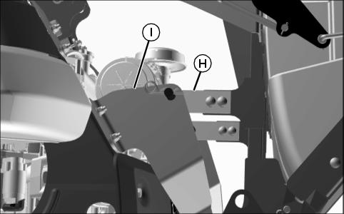
8. Pivot entire hopper assembly up toward machine until upper latches (H) align with brackets (I).
9. Install upper support bar (J) and a spring pin clip (K) on both ends of upper support bar.
Assemble Hopper
1. Remove tie strap from handle assembly.
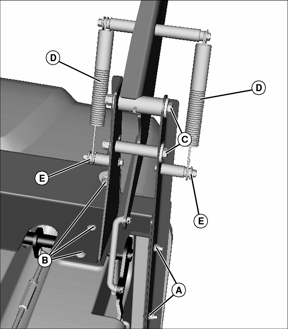
2. Place handle assembly in position onto hopper frame and install two M8x25 carriage bolts and M8 nuts at location (A). Do not tighten.
3. Install three M8X30 bolts, M8 washers and M8 nuts at location (B). Ensure handle assembly is flat against hopper frame and tighten all hardware.
4. Position handle into assembly and install two M12x110 hex head bolts, four washers, and two nuts (C).
5. Lift handle and position springs (D) to holders (E).
6. Ensure handle assembly is flat against hopper frame and tighten all hardware.
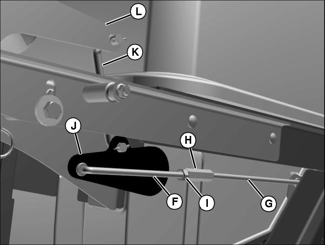
7. Install rods (F and G), turnbuckle (H), and jam nut (I) to left control shaft bellcrank (J) as shown. Secure rods with two M10 washers and cotter pins. Do not bend cotter pins at this time.
8. Install left door handle link (K) to bellcrank (J) and handle (L). Secure link with cotter pin. Do not bend cotter pin at this time.
9. Push door handle down so left door handle link (K) is over center of control shaft bellcrank as shown.
10. Adjust left door link turnbuckle (H) until door will not close any further. Door may have gap at bottom. Do not overtighten.
NOTE: Move door handle between open and closed positions while noting the over center force required to open door. It should take mild force to cause the door rod assembly (F-G) to move over center and open the door.
11. Lock jam nut (I) and disconnect door link from control shaft.
12. Install and adjust right door link assembly as in steps
4-8.
14. Connect left door link. Install and bend all cotter pins.
15. Check that the total opening force is not excessive. Adjust if necessary.
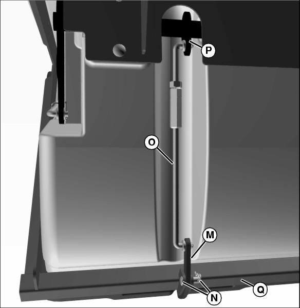
16. With door closed, install door catch (M) to frame with M10x28 clevis pin and spring pin (N).
17. Install latch link assemblies (O) to door catch (M) and bellcrank (P) with M10 washers and cotter pins.
18. Repeat procedure for other door catch assembly.
19. With door handle in closed position, adjust latch hook link turnbuckles so that the door catches rotate up and just touch the door catch bracket (Q). Tighten both jam nuts.

20. Loosen and adjust handle stop (N) so door remains open when handle is in fully open position.
Assemble Upper Chute
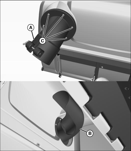
1. Install the outer (A) and inner (B) upper chute assembly to hopper using five M8x45 carriage bolts and locknuts (C). Tighten all hardware.
Assemble Lower Chute
1. Install lower chute connector bracket (A) on bottom of lower chute (B). Secure with M6 carriage bolts and locknuts.
Installing Deck Belt Shield
NOTE: For installation on 48 in. decks only.
1. Remove the spindle mounting bolt from location (A). Retain bolt for use if bagger is removed.
2. Insert spindle mounting bolt (B) up through spindle and deck.
3. Install spacer (C) onto spindle mounting bolt.
4. Secure spindle mounting bolt with nut (D).
5. Install belt shield (E) onto spindle mounting bolt and head pins.
6. Secure shield into place with nut (F) onto spindle mounting bolt.