
Installing
Install Blower
NOTE: The blower assembly weighs approximately 32 kg (70 lb).
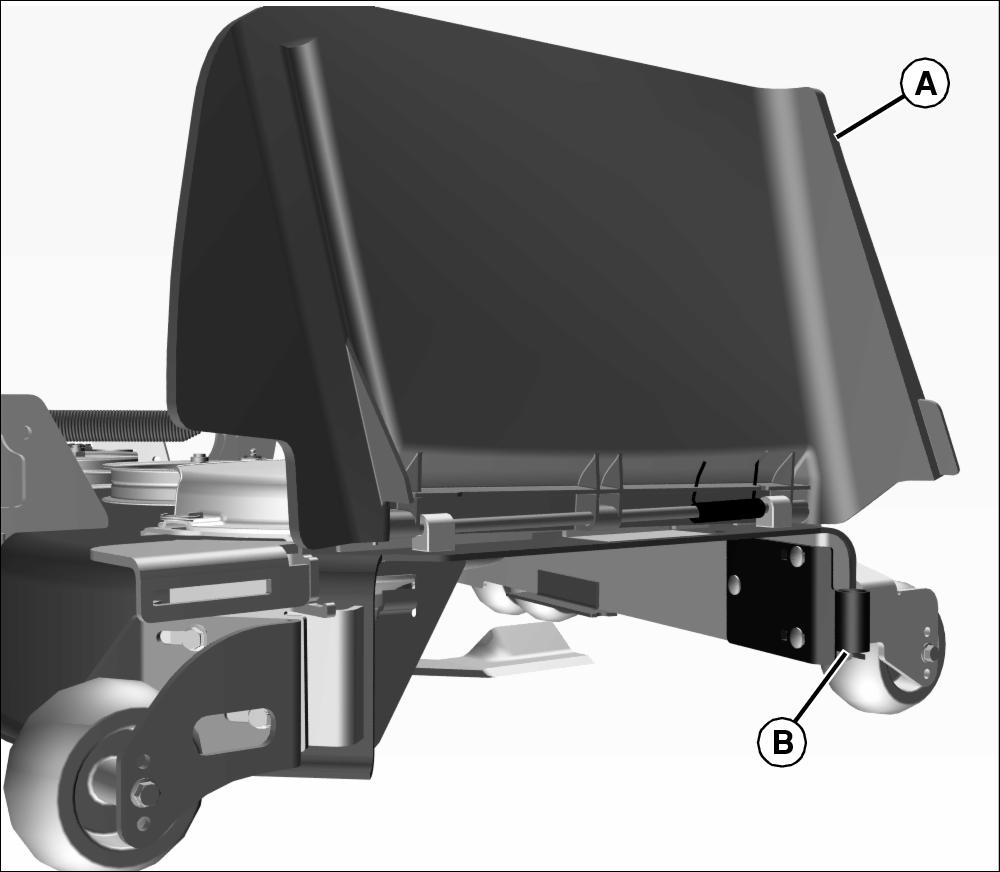
1. Lift discharge chute (A) and locate front mounting bracket (B).
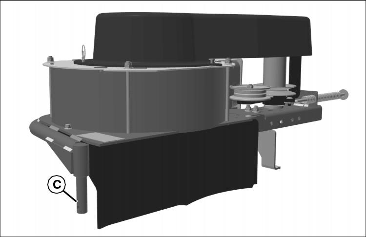
2. Insert front pivot pin (C) of blower into front bracket (B).
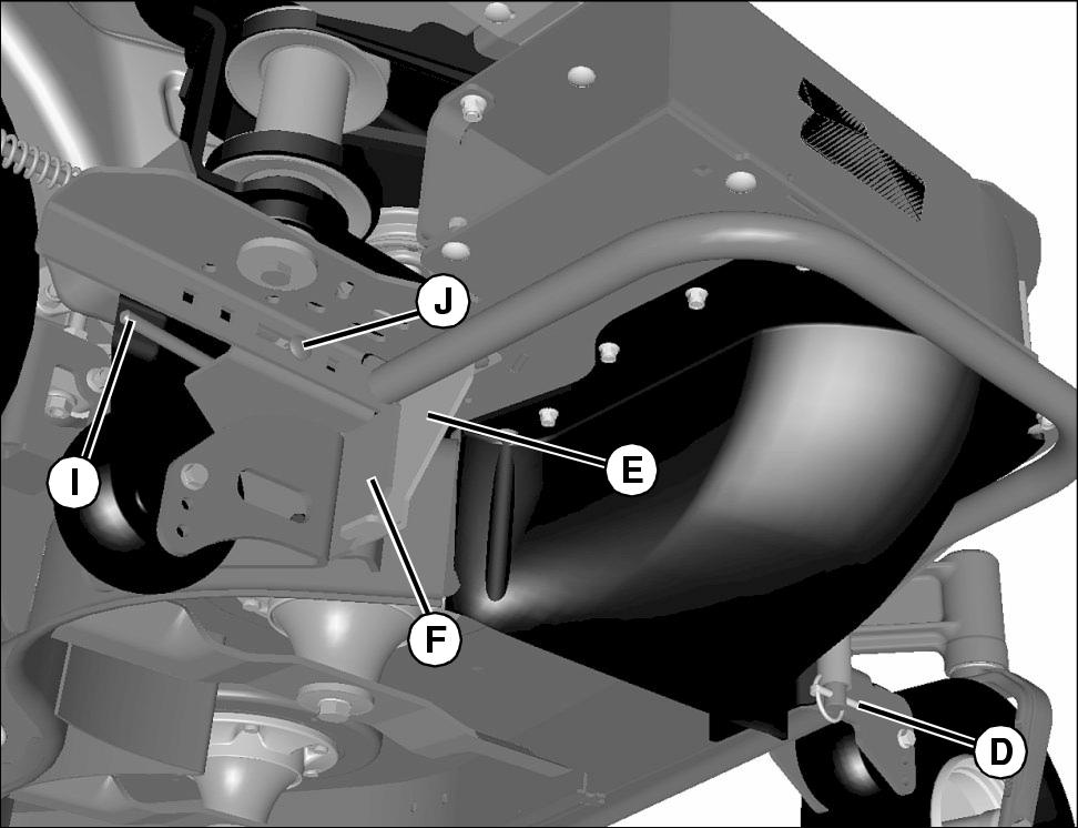
3. Install front lynch pin (D).
4. Rotate the blower in position so that the bottom blower plate (E) rests on top of the mounting bracket (F) at the rear of the blower. When mounting on 48 inch mower, blower plate does not rest on top of the mounting bracket.
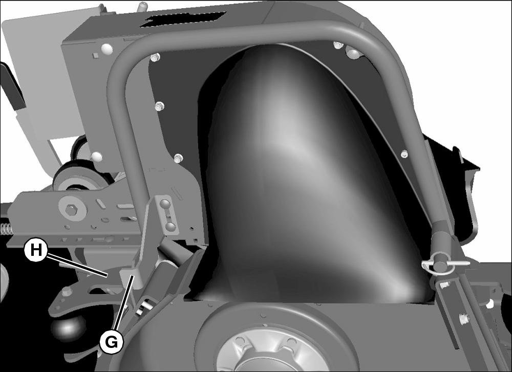
5. Mounting bracket (G) should meet anti-scalp wheel assembly (H) or deck.
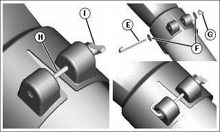
6. Secure in place with the mode change release handle (I) and M8x25 carriage bolt (J).
Picture Note: Parts have been removed for clarity.
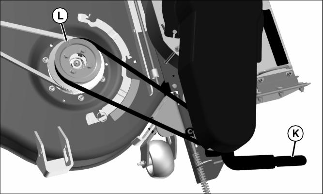
7. Use tension lever (K) to allow belt to slip over sheave (L).
8. Install correct blower belt shield for application.
Cutting Hose to Length
1. Cut hose to the length listed below for your mower deck size. Hose may already be correct length for some machine configurations, see chart to verify hose length. Edges of the hose may be sharp after cutting, file to smooth the edges if needed.
Installing Chute
Picture Note: Hex head bolt used in previous production models, J-bolt used in current production models.
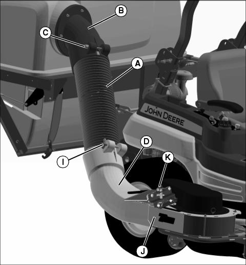
1. Connect hose (A) to upper chute assembly (B).
2. Secure hose to upper chute with bolt and knob (C).
3. Connect lower end of hose (A) to lower chute (D).
4. Secure hose to lower chute:
• Secure hose to lower chute with J-bolt (E), washers (F) and knob (G).
• Secure hose to lower chute with hex head bolt (H) and knob (I).
5. Lift and hold open exhaust flap on blower.
6. Slide lower chute (D) completely onto blower outlet (J), making certain pin (K) is fully lowered, securing lower chute onto blower.
7. Tighten knobs on upper and lower chutes to hold hose assembly in place.
Installing Ballast
• Ballast is not included with this kit but is required for safe operation. Refer to chart for specific requirements and see your authorized John Deere dealer for ordering.
• If installed, remove rear side weights from mower. Side weights are not compatible with the MCS.
• Weight bracket should remain on machine when operating with the MCS even if chart shows that no weights are required.
• Only Z800A with 60 and 72 in. decks: An additional suitcase weight is required on the machine if front pneumatic caster tires are installed in place of the original standard semi-pneumatic tires.
NOTE: If your model is not listed above, look in your power unit manual for information regarding a needed ballast.
Install the proper front ballast to help counterbalance the total weight of the bagger. Remove ballast when the bagger is removed. This will ensure proper operation of the machine when not bagging.
Installing Weight
NOTE: See Ballast Chart for the proper weight requirements for your machine.
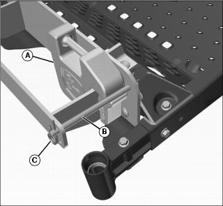
1. Install suitcase weight(s) (A) onto bracket.
NOTE: If the number of required weights is an odd number, add the odd number weight to the left side of machine (or opposite side of blower) to offset the weight of the blower assembly.
2. Slide the rod (B) over weight(s) to lock down.
3. Install locking pins (C) on rod.
Adjusting Deck Lift Spring Tension
NOTE: Deck lift springs are set at factory specs. When installing the MCS, the springs should be adjusted to the following specifications. When the MCS is removed, the springs should be set back to the original factory settings. Refer to machine operator’s manual for the correct factory settings without the MCS installed.
Check Spring Tension
1. Park machine on a hard, level surface.
2. Stop engine and lock park brake.
3. Raise the mower deck to the transport position.
NOTE: If your lift assist does not look like the assembly below, look at your power unit operator’s manual for adjustment procedure.
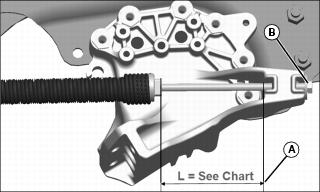
While looking from rear of machine:
• Turn hex nut (B) clockwise to increase deck lift spring tension.
• Turn hex nut (B) counterclockwise to decrease deck lift spring tension.