
Service Transmission
Transmission and Hydraulic Oil
NOTE: Tractor is filled with John Deere High Viscosity Hy-Gard™ (J20C) transmission oil at the factory.
Do not use type “F” automatic transmission fluid, J20D Low Viscosity Hy-Gard™, or Bio Hy-Gard™.
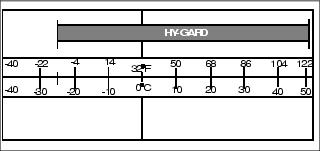
Use the following oil viscosity based on the air temperature range. Operating outside of the recommended oil air temperature range may cause premature hydrostatic transmission failure.
John Deere Hy-Gard™ (J20C) transmission oil is specially formulated to provide maximum protection against mechanical wear, corrosion, and foaming.
Checking Transmission Oil Level
IMPORTANT: Avoid damage! Hot hydraulic oil will expand and show incorrect oil level. Check oil level: |
NOTE: Do not overfill reservoir tank. Oil will expand during operation and could overflow.
1. Park machine safely. (See Parking Safely in the SAFETY section.)
2. Lift operator seat and lock into position.
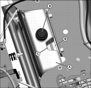
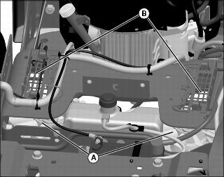
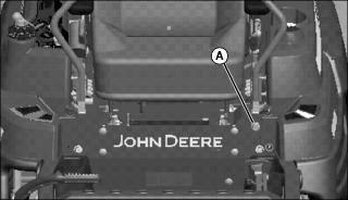
3. Check oil level in reservoir (A). Oil level should be between MIN (B) and MAX (C) on reservoir.
4. If oil is below MIN (B) on reservoir, remove cap (D) from reservoir and add oil until oil level is between MIN and MAX on reservoir.
5. Install cap on reservoir and hand tighten only. Do not overtighten cap.
Changing Transmission Oil and Filter
1. Park machine safely. (See Parking Safely in the SAFETY section.)
2. Allow engine and transmission oil reservoir to cool.
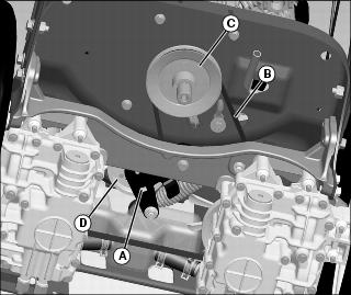
3. Remove filter cap (A) and filter from each transmission. Discard filter.
4. Allow transmission oil to drain into a drain pan.
5. Apply a film of clean oil on gasket of new filter.
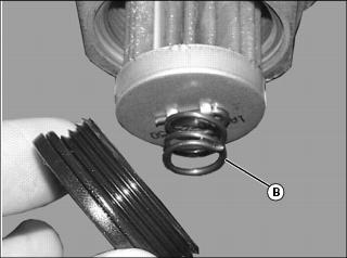
6. Install new filter into each transmission, with spring end (B) facing filter cap.
7. Replace o-ring on the filter cap.
8. Install filter cap (removed earlier) and tighten to 7.3-12.3 N•m (5.4-9 ft lb).
9. Lift operator seat and lock into position.
10. Fill reservoir until oil level is between MIN and MAX marks on reservoir. Lower seat.
12. Allow engine to idle for 1 minute at low idle before full throttle.
13. Move throttle lever to the 3/4 fast idle position.
15. Run engine in full throttle for five minutes and then cycle motion control levers forward and rearward several times. Check for leaks around filter.
16. Stop the engine. Check oil level. Add oil as necessary.
Cleaning Transmission Fan and Cooling Fins
• Clear work area of bystanders. • Wear eye protection when using compressed air for cleaning purposes. |
1. Park machine safely. (See Parking Safely in the SAFETY section.)
2. Lift operator seat and lock into position.
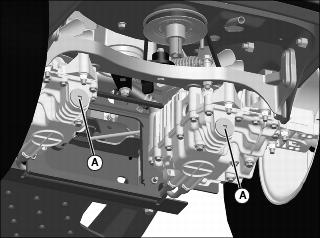
3. Clean cooling fins around exterior of transmissions and fans (A) with a rag, brush, or compressed air.
4. Clean transmission fan screens (B).
Checking and Replacing Traction Drive Belt
NOTE: The traction drive belt is self-adjusted using a spring tensioner and does not require a tension adjustment.
Checking Belt:
1. Park machine safely. (See Parking Safely in the SAFETY section.)
2. Inspect belt for excessive wear, damage or stretching while in position on the transmission sheave and drive belt tensioner sheave.
Replacing Belt
2. Insert a 1/2 in. drive extension tool into square hole (A) on tensioner arm, and rotate to release tension on belt (B).
3. While tensioner arm is rotated, remove traction drive belt from clutch pulley (C).
4. Remove belt from both transmission drive sheaves and idler sheave (D).
5. Install belt onto drive sheaves and idler sheave as shown.
Checking and Adjusting Neutral Creep
Checking Motion Control Linkages
1. Park machine safely. (See Parking Safely in the SAFETY section.)
2. Raise rear of machine only enough for rear tires to rotate freely.
4. Set throttle lever to the fast position.
6. If the rear drive wheels begin to creep, an adjustment is required.
Adjusting Motion Control Linkages
NOTE: Perform adjusts with rear tires off the ground just enough so wheels can rotate.
1. Stop engine and lock park brake.
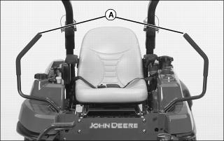
2. Move both motion control levers (A) to the neutral lock position.
5. Set throttle to fast idle position.
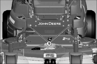
7. Locate left and right motion control linkage adjustment points (B).
8. Be sure the right motion control linkage is in the neutral lock position. The right drive wheel must not turn. If it does turn, adjust the motion control linkage.
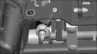
Picture Note: Front plate shown removed for clarity.
9. Adjust nut (C) on end of steering linkage.
• If wheel is spinning in forward direction, turn nut clockwise to bring wheel to a stop.
• If wheel is spinning in reverse direction, turn nut counter-clockwise to bring wheel to a stop.
10. Move the right motion control lever completely forward and rearward in the slot and then back to the neutral lock-out position.
• The drive wheels will slow down to +/- 4 rpm. If the drive wheels are rotating faster than +/- 4 rpm, repeat previous step.
11. Repeat procedure to adjust the left motion control linkage.
• Drive wheels should not rotate when in neutral lock position.
13. Move both motion control levers to the neutral lock position.
15. Dismount from the machine.
Adjusting Tracking
If the machine does not track in a straight line while going forward, adjust the tracking:
1. Park machine safely. (See Parking Safely in the SAFETY section.)
2. Turn the adjusting screw as required:
• If machine tracks to right, turn adjusting screw (A) clockwise one rotation.
• If machine tracks to left, turn adjusting screw (A) counter-clockwise one rotation.
3. Test vehicle for proper tracking.
4. Repeat the steps 2 and 3 as necessary to adjust the tracking.