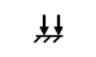
Down Force
A59325-UN-19FEB07
Menu
A59551-UN-08MAR07
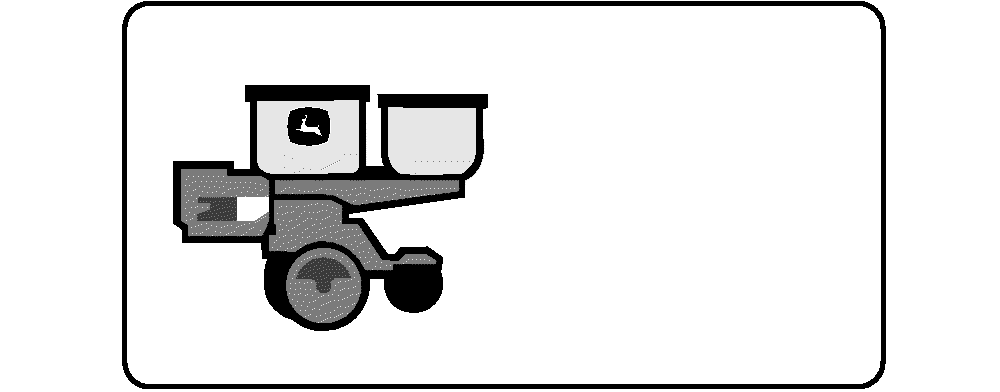
Planter Button
A72739-UN-23SEP11
Down Force Button (Single Set-Point PDF)
A72740-UN-23SEP11
Down Force Button (Dual Set-Point PDF)
A72767-UN-23SEP11
Down Force Button (Active PDF One Sensor)
A72768-UN-23SEP11
Down Force Button (Active PDF Two Sensors)
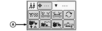
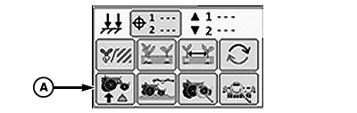
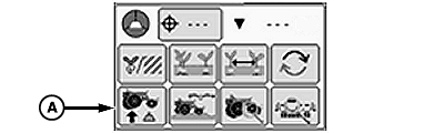
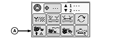
A - Down Force Button
Select Menu >> Planter button.
When down force button (A) is selected, the down force at a glance screen is displayed.
The Down Force run screen displays average gauge wheel down force margin for each row unit equipped with a sensor node controller and gauge wheel down force sensor.
The gauge wheel down force sensor measures the amount of load that the gauge wheels are carrying as the row units move through the field. The load on the gauge wheels changes frequently when the planter is in motion and is displayed as margin on the display.
Down force margin is the amount of extra down force being applied to the row unit, over and above what is required for the opener disks to penetrate the soil and achieve full planting depth. The extra down force can come from the weight of the row unit and meter, weight of seed in the seed hoppers, the pneumatic down force system, or external down force springs.
IMPORTANT: Always perform and in field check BEFORE adjusting the target down force margin. Once depth and seed furrow has been verified, target margin can be adjusted accordingly.
A target down force margin must be entered based on the operator's judgment of planting conditions. Refer to ALARMS AND LIMITS SETUP PAGE in SeedStar™ XP SETUP Enhanced Monitor System section. Set down force margin high enough to create a defined seed furrow but not so high that the side wall of the furrow is compacted.
High and Low Margin alarm set points are defined on the Alarms and Limits Setup Page. The margin alarm activates if the planter average down force margin goes above or below the target margin by the amount entered on the Alarms and Limits Setup Page.
The center line of the Down Force at a Glance chart is the target margin. Down Force at a Glance bars above the center line indicate down force margin above the target set point. Bars below the center line indicate down force margin below the target set point. If down force margin is consistently low on monitor screen, increase pneumatic row unit down force setting or reduce target margin set point based on your judgment of planting conditions and uniformity of seed depth. If down force margin is consistently high on monitor screen, decrease pneumatic row unit down force setting or increase target margin set point.
IMPORTANT: To ensure down force sensor accuracy, zero sensors annually or whenever sensors do not read 0 lbs. when planter is raised.
A72706-UN-20SEP11
The operator selects a desired down force target that produces the most optimal seed furrow. When soil conditions change the operator can increase or decrease the pneumatic down force to maintain target margin, depth control, and avoid compacting the furrow.
Data from the row unit gauge wheel sensors is sent to the Planter Main 2 (PM2) controller and then displayed as down force margin on the monitor.
IMPORTANT: Always perform and in field check BEFORE adjusting the target down force margin. Once depth and seed furrow has been verified, target margin can be adjusted accordingly.
A72708-UN-21SEP11
The operator selects a desired target margin (the amount of extra down force applied to the row unit, over and above what is required for the opener disks to penetrate the soil and achieve full planting depth). Active Down Force automatically monitors and adjusts the air pressure in the air springs to ensure that the actual margin is equal to the target margin. When soil conditions change, the active down force system automatically adjusts the down force to achieve the target margin.
IMPORTANT: Always perform and in field check BEFORE adjusting the target down force margin. Once depth and seed furrow has been verified, target margin can be adjusted accordingly.
A73458-UN-03NOV11
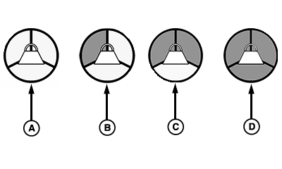
A - No Activity
B - Sensor Diagnostic Check OK
C - Wheel Motion Sensor Active
D - Planter Lowered (System Active)
Three requirements must be met for the Active Down Force system to function properly.- Sensor diagnostic check OK.
- Wheel motion sensor active, the machine must be moving at a least 1.6 km/h (1 mph).
- Machine must be lowered in the planting position.
Initially, the Active Down Force icon is empty. As the three requirements are met, the corresponding segments of the icon turn from blank to gray. After all the requirements are met, the entire icon will turn green, indicating that the PDF system is enabled, and active.
Single Set-Point Pneumatic Down Force
A73029-UN-13OCT11
A73031-UN-13OCT11
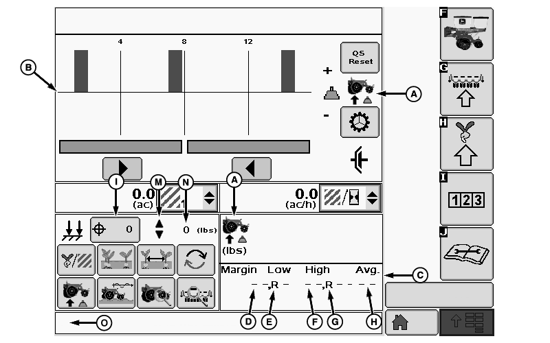
A - Down Force Icon
B - Down Force Margin Graph
C - Numeric Down Force Margin Details
D - Low Margin Value
E - Low Margin Row
F - High Margin Value
G - High Margin Row
H - Average Margin
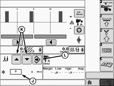
I - Down Force Target Button
J - Down Force Input Box
K - Increase and Decrease Arrows
L - Enter Button
M - Indicator Arrows
N - Actual Down Force
O - Warning Message Area
(A) Down force icon.
(B) Down force margin bar graph.
(C) Numeric down force margin details contains the information of the current bar graph.
(D) Low margin value displays the lowest down force margin value obtained by the gauge wheel sensors.
(E) Low margin row displays the row unit associated with the lowest down force margin.
(F) High margin value displays the highest down force margin value obtained by the gauge wheel sensors.
(G) High margin row displays the row unit associated with the highest down force margin.
(H) Average Margin displays the average down force margin of all the gauge wheel sensor data.
Setting Target Down Force
- Select the down force target button (I) to open the target down force input screen.
- Set target row unit down force by using the target down force input box (J) or the increase or decrease arrows (K).
- When complete select enter (L).
- Indicator arrows (M) are displayed as a visual indication that the system is increasing or decreasing pneumatic down force pressure.
- Actual down force (N) is checked on a timed interval and automatically adjusted if necessary to match the target down force. If Actual down force (N) deviates below the target at an unacceptable rate, a warning appears in the warning message area (O) stating "Check pneumatic down force for leaks". Depending on the severity of the leak, the actual down force number (N) is highlighted orange or red.
Screen Area Information
QS Reset - QS Reset
Dual Set-Point Pneumatic Down Force
A73032-UN-13OCT11
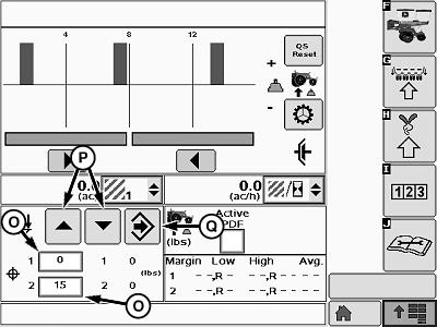
A73033-UN-13OCT11
A - Down Force Icon
B - Down Force Margin Graph
C - Numeric Down Force Margin Details
D - Low Margin Value—Rank 1
E - Low Margin Row—Rank 1
F - Low Margin Value—Rank 2
G - Low Margin Row—Rank 2
H - High Margin Value—Rank 1
I - High Margin Row—Rank 1
J - High Margin Value—Rank 2
K - High Margin Row—Rank 2
L - Average Margin—Rank 1
M - Average Margin—Rank 2
N - Down Force Target Button
O - Down Force Input Box
P - Increase and Decrease Arrows
Q - Enter Button
R - Indicator Arrows
S - Actual Down Force
T - Warning Message Area
(A) Down force icon.
(B) Down force margin bar graph.
(C) Numeric down force margin details contains the information of the current bar graph.
(D) Low margin value displays the lowest down force margin value obtained by the gauge wheel sensors on rank 1.
(E) Low margin row displays the row unit on rank 1 associated with the lowest down force margin.
(F) Low margin value displays the lowest down force margin value obtained by the gauge wheel sensors on rank 2.
(G) Low margin row displays the row unit on rank 2 associated with the lowest down force margin.
(H) High margin value displays the highest down force margin value obtained by the gauge wheel sensors on rank 1.
(I) High margin row displays the row unit on rank 1 associated with the highest down force margin.
(J) High margin value displays the highest down force margin value obtained by the gauge wheel sensors on rank 2.
(K) High margin row displays the row unit on rank 2 associated with the highest down force margin.
(L) Average Margin displays the average down force margin of all the gauge wheel sensor data on rank 1.
(M) Average Margin displays the average down force margin of all the gauge wheel sensor data on rank 2.
Setting Target Down Force
- Select the down force target button (N) to open the target down force input screen.
- Set target row unit down force by using the target down force input boxes (O) or the increase or decrease arrows (P).
- When complete select enter (Q).
- Indicator arrows (R) are displayed as a visual indication that the system is increasing or decreasing pneumatic down force pressure.
- Actual down force (S) is checked on a timed interval and automatically adjusted if necessary to match the target down force. If Actual down force (S) deviates below the target at an unacceptable rate, a warning appears in the warning message area (T) stating "Check pneumatic down force for leaks". Depending on the severity of the leak, the actual down force number (S) is highlighted orange or red.
Screen Area Information
QS Reset - QS Reset
Active Pneumatic Down Force (Single Rank)
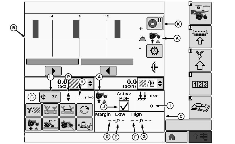
A73030-UN-13OCT11
A73028-UN-13OCT11
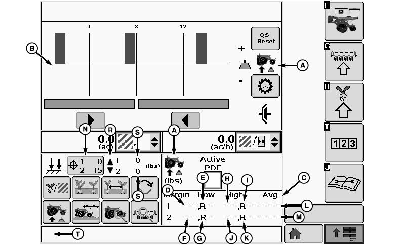
A - Down Force Icon
B - Down Force Margin Graph
C - Numeric Down Force Margin Details
D - Low Margin Value
E - Low Margin Row
F - High Margin Value
G - High Margin Row
H - Actual Margin
I - Actual Down Force
J - Active PDF Check Box
K - Active PDF Pause Button
L - Margin Target Button
M - Target Margin Input Box
N - Increase and Decrease Arrows
O - Enter Button
P - Indicator Arrows
(A) Down force icon.
(B) Down force margin bar graph.
(C) Numeric down force margin details contains the information of the current bar graph.
(D) Low margin value displays the lowest down force margin value obtained by the gauge wheel sensors.
(E) Low margin row displays the row unit associated with the lowest down force margin.
(F) High margin value displays the highest down force margin value obtained by the gauge wheel sensors.
(G) High margin row displays the row unit associated with the highest down force margin.
(H) Actual margin displays the average margin of all the gauge wheel down force sensor data.
(I) Actual down force
(J) Active PDF check box is used to enable and disable the active down force system. When active PDF is disabled the system operation characteristics reverts back to those characteristics of the set-point system, and does not make any automatic down force adjustments.
(K) Active PDF pause button allows the operator to disable the active pneumatic down force system temporarily for a pre-determined amount of time. Time duration is set in the Alarms and Limits Screen.
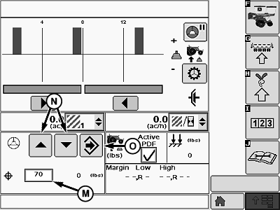
Setting Target Margin
- Select the margin target button (L) to open the target margin input screen.
- Set target margin by using the target margin input box (M) or the increase or decrease arrows (N).
- When complete select enter (O).
- Indicator arrows (P) are displayed as a visual indication that the system is increasing or decreasing pneumatic down force pressure.
- In Active mode, the system automatically makes down force adjustments to compensate for variations in the soil to maintain the target margin.
Active Pneumatic Down Force Dual Rank (Split Row)
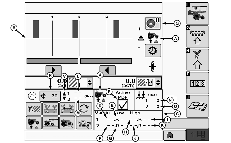
A73049-UN-19OCT11
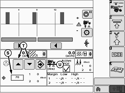
A73035-UN-13OCT11
A - Down Force Icon
B - Down Force Margin Graph
C - Numeric Down Force Margin Details
D - Low Margin Value—Rank 1
E - Low Margin Row—Rank 1
F - Low Margin Value—Rank 2
G - Low Margin Row—Rank 2
H - High Margin Value—Rank 1
I - High Margin Row—Rank 1
J - High Margin Value—Rank 2
K - High Margin Row—Rank 2
L - Actual Margin—Rank 1
M - Actual Margin—Rank 2
N - Actual Down Force—Rank 1
O - Actual Down Force—Rank 2
P - Active PDF Check Box
Q - Active PDF Pause Button
R - Margin Target Button
S - Target Margin Input Box
T - Increase and Decrease Arrows
U - Enter Button
V - Indicator Arrows
(A) Down force icon.
(B) Down force margin bar graph.
(C) Numeric down force margin details contains the information of the current bar graph.
(D) Low margin value displays the lowest down force margin value obtained by the gauge wheel sensors on rank 1.
(E) Low margin row displays the row unit on rank 1 associated with the lowest down force margin.
(F) Low margin value displays the lowest down force margin value obtained by the gauge wheel sensors on rank 2.
(G) Low margin row displays the row unit on rank 2 associated with the lowest down force margin.
(H) High margin value displays the highest down force margin value obtained by the gauge wheel sensors on rank 1.
(I) High margin row displays the row unit on rank 1 associated with the highest down force margin.
(J) High margin value displays the highest down force margin value obtained by the gauge wheel sensors on rank 2.
(K) High margin row displays the row unit on rank 2 associated with the highest down force margin.
(L) Actual margin displays the average margin of all the gauge wheel down force sensor data for rank 1.
(M) Actual margin displays the average margin of all the gauge wheel down force sensor data for rank 2.
(N) Actual down force rank 1
(O) Actual down force rank 2.
(P) Active PDF check box is used to enable and disable the active down force system. When active PDF is disabled the system operation characteristics reverts back to those characteristics of the set-point system, and does not make any automatic down force adjustments.
(Q) Active PDF pause button allows the operator to disable the active pneumatic down force system temporarily for a pre-determined amount of time. Time duration is set in the Alarms and Limits Screen.
Setting Target Margin
- Select the margin target button (R) to open the target margin input screen.
- Set target margin by using the target margin input box (S) or the increase or decrease arrows (T).
- When complete select enter (U).
- Indicator arrows (V) are displayed as a visual indication that the system is increasing or decreasing pneumatic down force pressure.
- In Active mode, the system automatically makes down force adjustments to compensate for variations in the soil to maintain the target margin.
|
OUO6064,00005ED-19-20111110 |