Down Force Sensor Configuration
-
NOTE:

A59325-UN-19FEB07Menu
A59551-UN-08MAR07Planter Button
A59172-UN-29JAN07Configuration Softkey
A59369-UN-20FEB07Zero Sensor Button
Changing the sensor and row values on the Down Force screen also changes the Down Force configuration screen.Select Menu >> Planter button >> Configuration softkey >> Sensor tab.
-
Select Down Force from drop-down box.
-
Select number of down force sensors on machine from # of Sensors: drop-down box.
-
Select each sensor, one at a time, from the Sensor drop-down box.
-
Identify which row the first sensor is installed. See Sensor Quantities and Locations chart. Select Row and assign the row number to the selected sensor.
-
NOTE: The Rank input box only appears when the Planter Main 2 (PM2) controller detects the PDF1 enabled signal, indicating the presence of a hydraulic compressor.
Select a rank for each sensor from the Rank drop-down box. See Sensor Quantities and Locations chart for rank information.
-
Select Enable check box to enable or disable the sensor.
-
NOTE: When planting with only the front rank of a split row planter, disable all sensors on the rear rank.
Select Cal Value input box and enter the down force sensor calibration value.John Deere™ planters with factory equipped sensors have a calibration value of 1394.
NOTE: Current load is displayed on bottom left of screen.
-
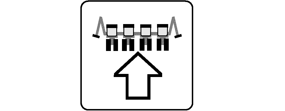
NOTE: To zero down force sensors, planter must be raised and stopped.
Select Zero Sensor button.
-
Repeat row assignment for more sensors.
|
Sensor Quantities and Locations |
||
|---|---|---|
|
Planter Model |
Quantity of Sensor Nodes and Down Force Sensors |
Row Location of Sensor Nodes and Down Force Sensors2 |
|
Custom Built 12 Row |
3 |
2, 7, 11 |
|
Custom Built 16 Row |
3 |
3, 9, 14 |
|
Custom Built 18 Row |
3 |
3, 10, 16 |
|
1720 and 1725 16 Row 76 cm (30 in.) spacing |
3 |
3, 9, 14 |
|
1720 CCS and 1725 CCS 12X2 Twin Row |
3 |
4, 14, 22 |
|
1770NT and 1775NT 12 Row 76 cm (30 in.) spacing |
3 |
2, 7, 11 |
|
1770NT and 1775NT 16 Row 76 cm (30 in.) spacing |
3 |
3, 9, 14 |
|
1770NT, 1775NT, and DB60 24 Row 76 cm (30 in.) spacing |
5 |
3, 7, 13, 18, 22 |
|
1790 and 1795 12/23 Row |
5 |
Front Rank (1) Rows 3, 13, 21 Rear Rank (2) Rows 4, 20 |
|
1790 and 1795 12/24 Row |
5 |
Front Rank (1) Rows 4, 14, 22 Rear Rank (2) Rows 5, 21 |
|
1790 and 1795 16/31 Row |
5 |
Front Rank (1) Rows 3, 17, 29 Rear Rank (2) Rows 8, 24 |
|
1790 and 1795 16/32 Row |
5 |
Front Rank (1) Rows 4, 18, 30 Rear Rank (2) Rows 9, 25 |
|
1790 and 1795 24 Row 51 cm (20 in.) spacing |
3 |
3, 13, 22 |
|
DB44 24 Row 56 cm (22 in.) spacing |
3 |
3, 13, 22 |
|
DB58 32 Row 56 cm (22 in.) spacing |
5 |
3, 10, 17, 23, 30 |
|
DB60 24R30 |
5 |
3, 7, 13, 18, 22 |
|
DB60 36 Row 51 cm (20 in.) spacing |
5 |
3, 11, 19, 26, 34 |
|
DB60 47 Row 38 cm (15 in.) spacing |
5 |
Front Rank (1) Rows 5, 25, 43 Rear Rank (2) Rows 14, 34 |
|
DB60 72 Row 51 cm (20 in.) Twin Row |
5 |
7, 20, 37, 54, 60 |
|
DB66 36 Row 56 cm (22 in.) spacing |
5 |
3, 11, 19, 26, 34 |
|
DB80 32 Row 76 cm (30 in.) spacing |
7 |
3, 7, 12, 17, 21, 26, 30 |
|
DB80 48 Row 51 cm (20 in.) spacing |
7 |
3, 10, 17, 25, 32, 39, 46 |
|
DB88 48 Row 56 cm (22 in.) spacing |
7 |
3, 10, 17, 25, 32, 39, 46 |
|
DB90 36 Row 76 cm (30 in.) spacing |
7 |
3, 8, 13, 19, 24, 29, 34 |
|
DB120 48 Row 76 cm (30 in.) spacing |
7 |
3, 10, 17, 25, 32, 39, 46 |
Screen Area Information
Planter Configuration - Planter Configuration
Down Force - Down Force
Sensors: - Sensors:
Sensor - Sensor
Row - Row
Enable - Enable
Cal Value - Calibration Value
lbs - Pounds
|
John Deere is a trademark of Deere & Company 1 Pneumatic Down Force 2 Row locations for sensor nodes and down force sensors can be moved one row-unit next to the factory-installed placement for desired application. |
WP29706,0000353-19-20150213 |