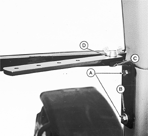
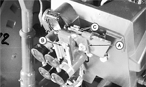
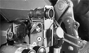
6000 Series Tractors-Console Installation1. Install mounting bracket (A) with two M10 x 20 screws with flat washer on slot (B). 2. Thread M10 x 30 bolt (C) into bracket and install monitor mounting strap with M10 wing nut (D).
|
|
AG,OUO1074,860 -19-01MAR00-1/7 |
|
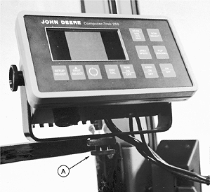
3. Mount monitor console to monitor strap with threaded knob (A).
|
|
AG,OUO1074,860 -19-01MAR00-2/7 |
|
|
|
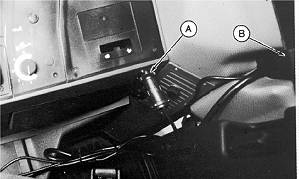
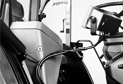
4. (Monitors With 2.7 m (9 ft.) Harness) Tie harness to door gas cylinder anchor (A) and route along side of right-hand console. |
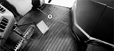
5. (Monitors With 4.6 m (15 ft.) Harness) Route under floor mat along side of right-hand console as shown (B). |
AG,OUO1074,860 -19-01MAR00-3/7 |
|
6. Connect power harness to rear convenience outlet (A). 7. (250 Monitor Only) Route main harness and radar harness through right-hand grommet (B).
|
|
AG,OUO1074,860 -19-01MAR00-4/7 |
|
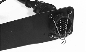
8. Install connector mounting spade to monitor harness connector using four self tapping screws (A).
|
|
AG,OUO1074,860 -19-01MAR00-5/7 |
|
9. Install rear connector mounting bracket (A) to tractor bracket as shown. 10. Install bracket with hex head against socket (B). 11. Use large washer over large hole in tractor bracket (C).
|
|
AG,OUO1074,860 -19-01MAR00-6/7 |
|
12. Install monitor connector with spade into socket (A). 13. Coil and band excess harness behind cab. 14. Connect radar harness from radar to monitor radar harness outside cab. Keep radar connector outside cab for easy monitor removal. NOTE: Put harness under SMV first, then loop harness and install spade in socket. 15. Position grommet on harness and caulk with rubber sealant.
|
|
AG,OUO1074,860 -19-01MAR00-7/7 |
