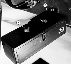
6000 Series Tractors with Exhaust on Hood-Radar and Bracket Installation1. Remove toolbox (A) and disassemble bracket (B).
|
|
AG,OUO1074,862 -19-01MAR00-1/4 |
|
|
|
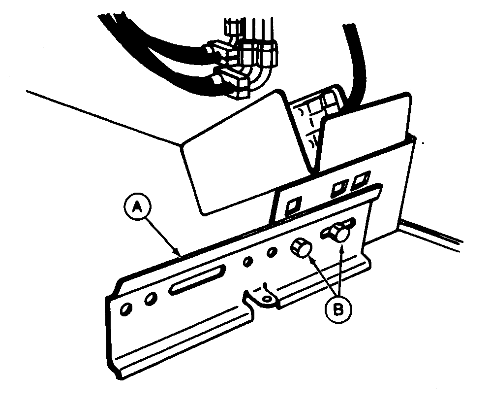
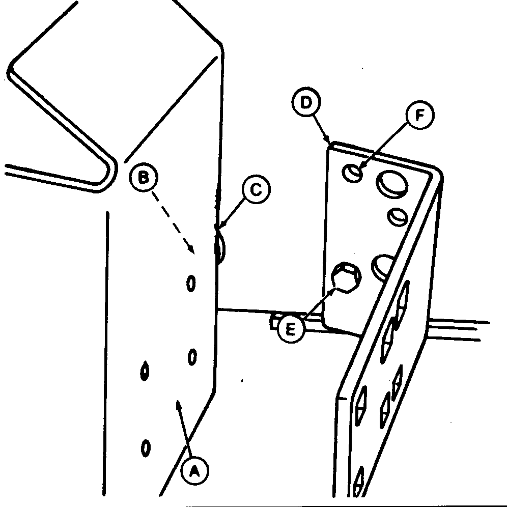
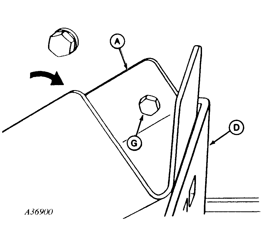
NOTE: Use M12 nuts provided if tractor frame holes are not threaded. 2. Install radar mounting bracket (A) with one M12 x 35 cap screw (B) and spacer (C). (Do not tighten cap screw.) 3. Install tool box bracket (D) with M12 x 35 cap screw (E). Line up top hole (F) with hole in tractor frame as illustrated. 4. Rotate radar mounting bracket (A) and line up holes in both brackets and insert M12 x 35 cap screw (G). TIGHTEN ALL MOUNTING HARDWARE. |
|
AG,OUO1074,862 -19-01MAR00-2/4 |
|
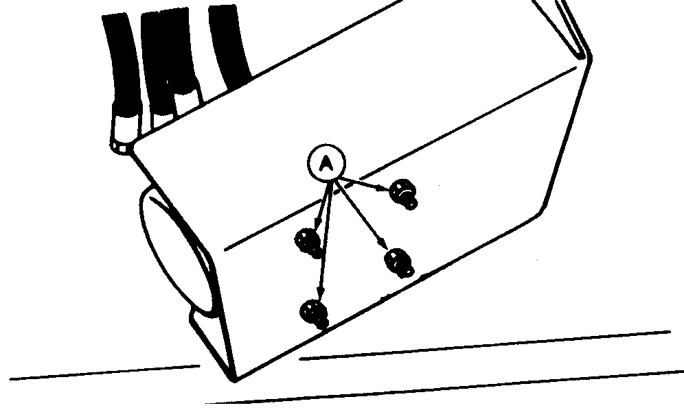
5. Radar must be mounted with serial number tag facing up. Attach with four 1/4 x 4 in. cap screws, four washers and four lock nuts (A). Washers are installed between bracket and lock nuts. 6. Route harness past cab side tipping hinge to rear of cab and connect to radar power harness. Secure with plastic self locking bands.
7. Nominal calibration for this radar installation is 7776. Radar points 7 degrees to side to miss rear tire. Calibration is less than other radars at 7836. |
|
AG,OUO1074,862 -19-01MAR00-3/4 |
|
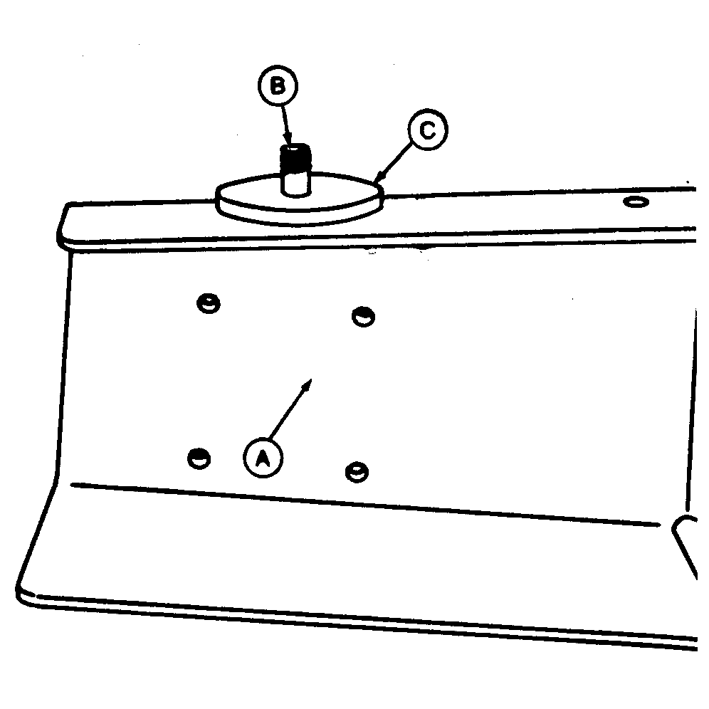
8. Install tool box bracket (A) as shown using existing hardware (B) and install tool box.
|
|
AG,OUO1074,862 -19-01MAR00-4/4 |
 CAUTION:
Avoid looking directly into the sensor face of radar to prevent possible eye damage from microwave signal emitted from radar sensor.
