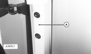
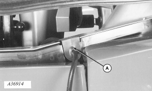
8000 Series Tractors-Console Installation1. Unscrew plastic covers from right-hand front post (A) and remove. (Already removed in illustration.)
|
|
AG,OUO1074,865 -19-01MAR00-1/11 |
|
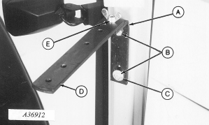
2. Install "L" bracket (A) on front post with two M10 x 20 cap screws (B) with flat washer (C) on lower cap screw. 3. Install monitor strap (D) with M10 x 30 round head bolt and wing nut (E), with strap hole spacing as shown.
|
|
AG,OUO1074,865 -19-01MAR00-2/11 |
|
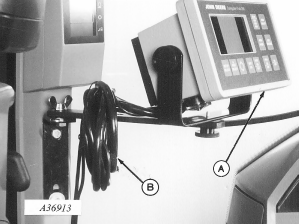
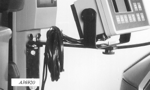
4. Mount monitor (A) to strap as illustrated. 5. Coil excess harness (B) around strap. 6. Route monitor harness along right window and behind instrument panel.
|
|
AG,OUO1074,865 -19-01MAR00-3/11 |
|
7. Remove existing right-hand side grommet. Install harness in new grommet (provided) and install grommet (A).
|
|
AG,OUO1074,865 -19-01MAR00-4/11 |
|
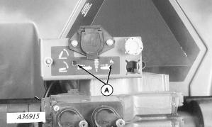
8. Cut holes (A) in decal.
|
|
AG,OUO1074,865 -19-01MAR00-5/11 |
|
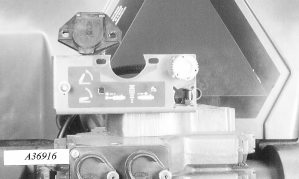
9. Remove two cap screws attaching 7-pin connector and discard. |
|
AG,OUO1074,865 -19-01MAR00-6/11 |
|
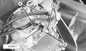
10. Install sockets (A) with M8 x 16 round head bolts, flat washers and nuts. DO NOT tighten until all hardware is in place. 11. Install two M8 x 55 cap screws (B), spacer (C), and 7-pin connector (D) with flat washers against connector plastic (E) and nuts. Tighten hardware.
|
|
AG,OUO1074,865 -19-01MAR00-7/11 |
|
12. Attach harness to connector spade using four self-tapping screws (A).
|
|
AG,OUO1074,865 -19-01MAR00-8/11 |
|
13. Install connector spade (A) into socket and push down to seat.
|
|
AG,OUO1074,865 -19-01MAR00-9/11 |
|
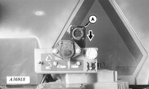
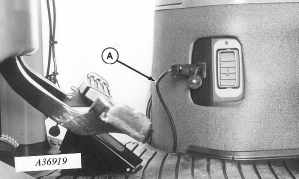
NOTE: Harness may be installed in rear outlet. 14. Install monitor power harness (A) into front convenience outlet if equipped. 15. Route harness under floor mat. 16. Nylon tie excess main and power harness to monitor strap.
|
|
AG,OUO1074,865 -19-01MAR00-10/11 |
|
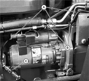
17. Route harness (A) along air conditioner lines and behind starter. 18. Attach harness to lines with tie straps (B).
NOTE: Once radar is connected to tractor harness, radar supplies tractor instrumentation and radar signal is available for monitor from 2-pin connector at right-hand console. 19. Connect signal harness to radar harness at (C).
|
|
AG,OUO1074,865 -19-01MAR00-11/11 |

 CAUTION:
Avoid looking directly into the sensor face of radar to prevent possible eye damage from microwave signal emitted from radar sensor.
