Frame Flexibility (10- and 12-Row Wide)-1720
|
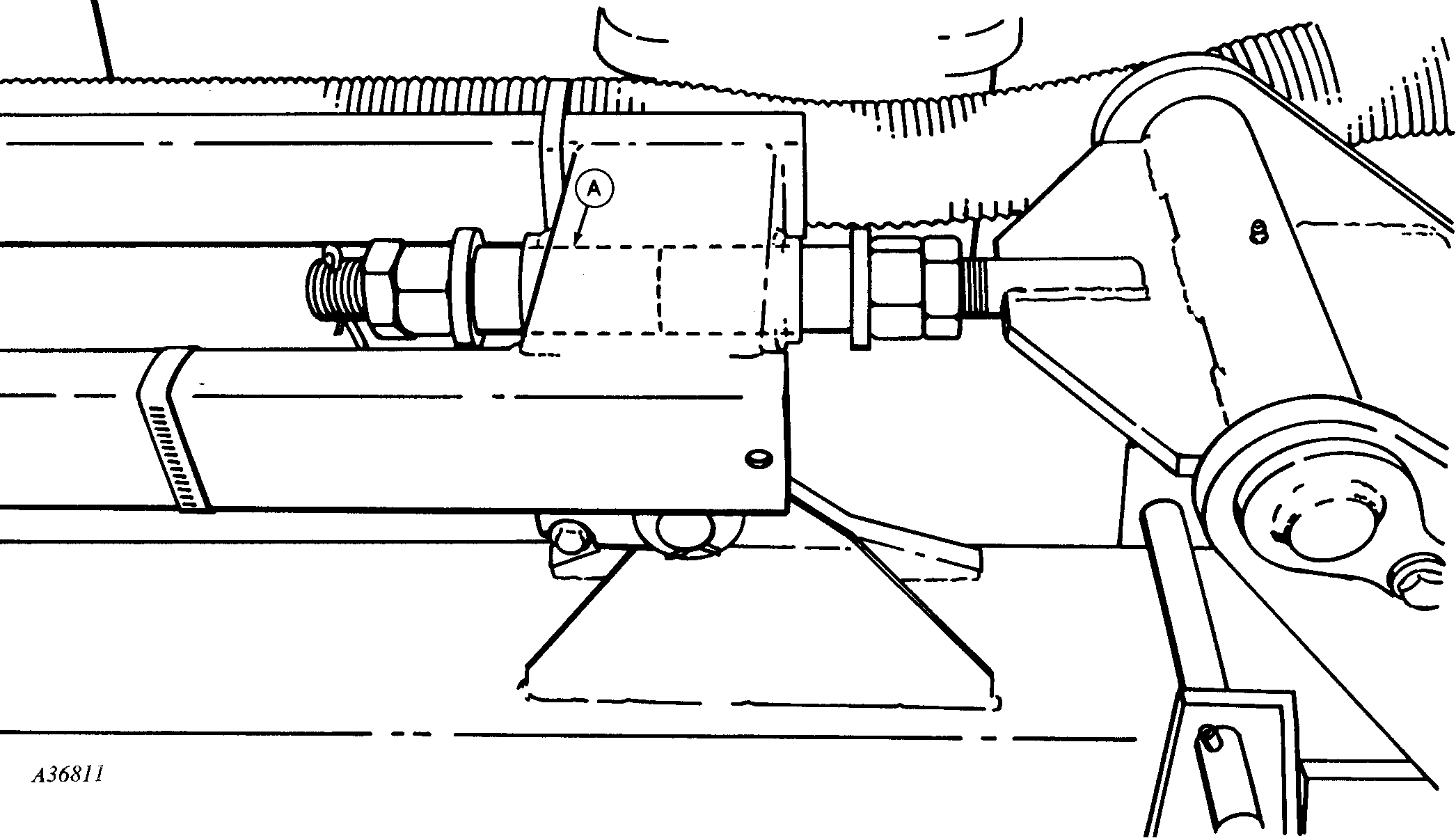
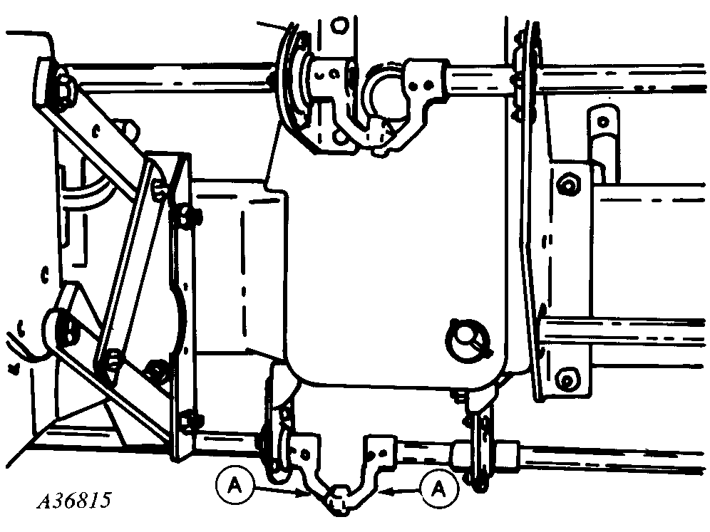
1.
Position planter frame on a smooth, level surface in an unfold (planting) position; then cut a 4-9/16 in. (116 mm) long plastic spacer from SHC40 PVC and install next to existing spacer on trunnion at (A).
|
Adjust nuts so an equal amount of spacer is exposed at each end of link sleeve. This allows the wing frame to flex five degrees up and down.
|
|
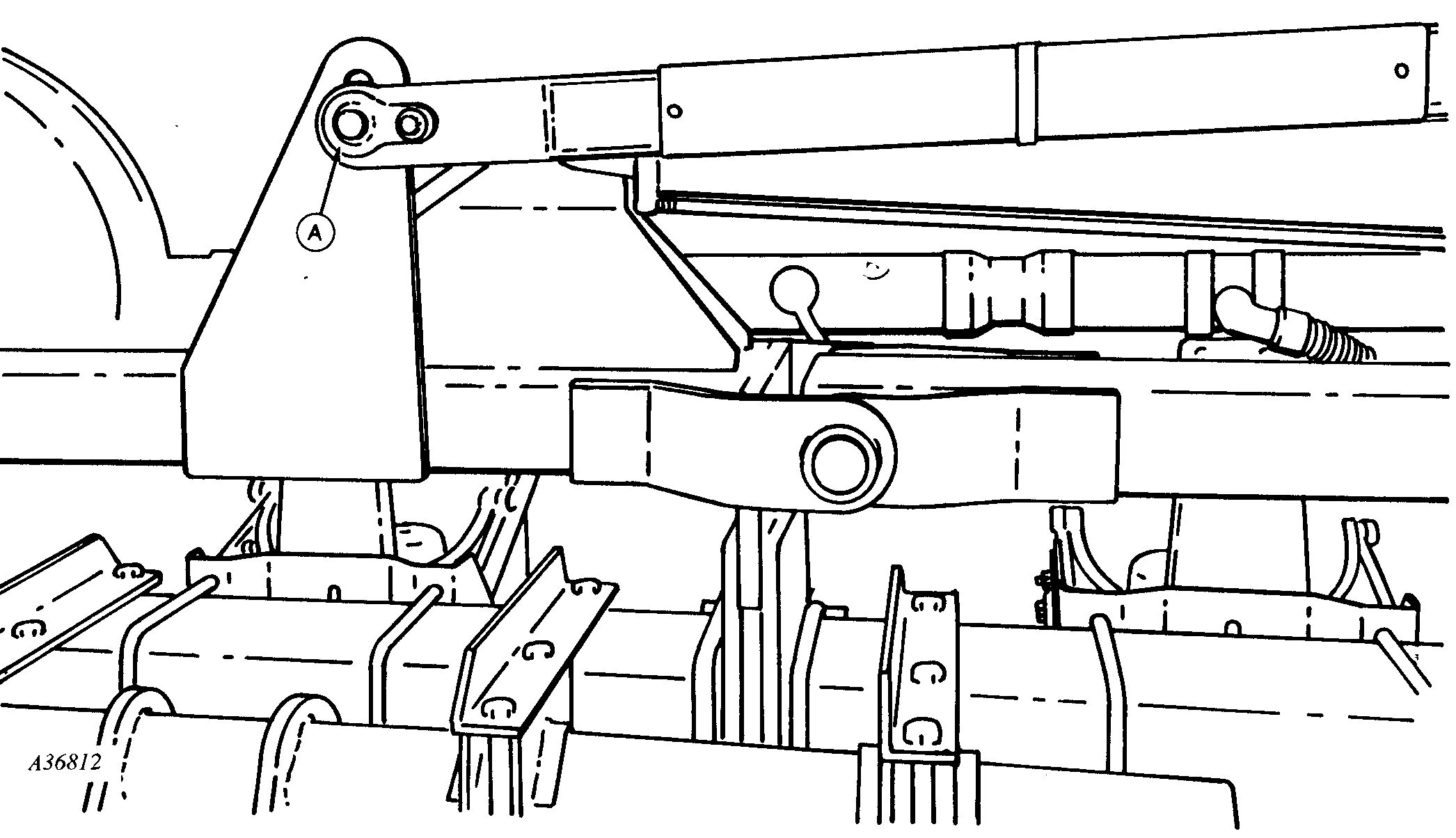
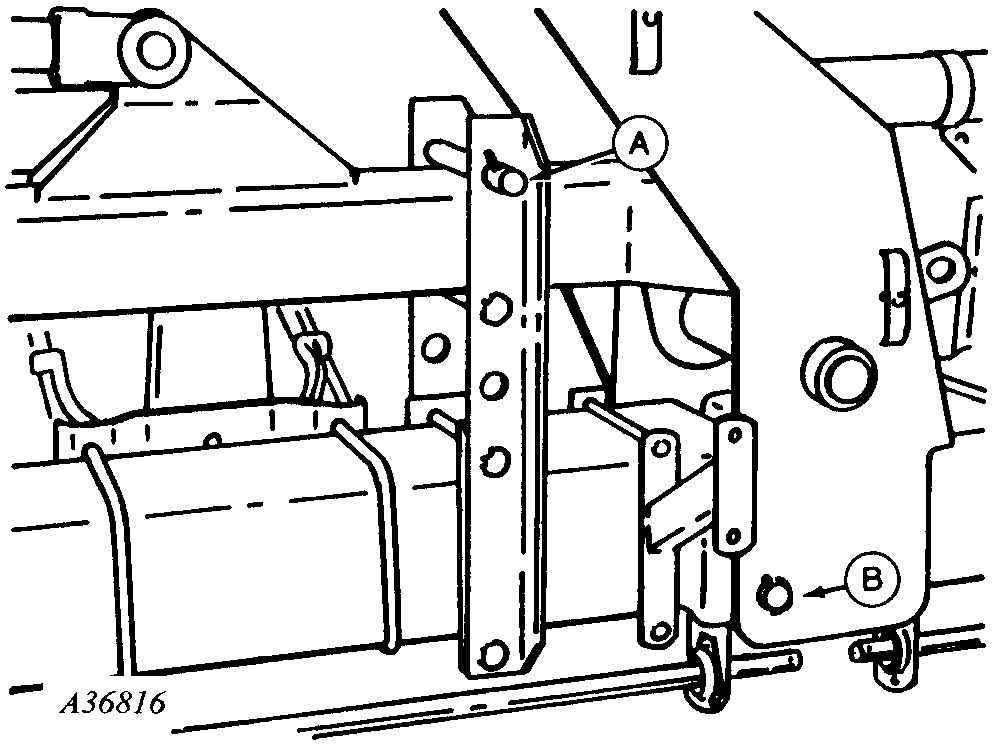
2.
Remove link pin (A), reposition link and install pin in lower hole.
|
|
|
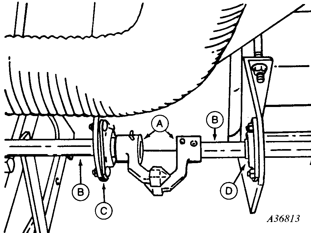
3.
Look down on drillshaft coupler (A) and check fore-and-aft alignment. Shafts (B) must align within 5 mm (3/16 in.) of one another. Reposition bearing support (C) or (D) (if necessary) to align.
Check drillshaft couplers (A) for vertical alignment. Shaft (B) must align within 5 mm (3/16 in.) of one another.
Repeat for right-hand side of planter.
A-Coupler
B-Shafts
C-Support, Bearing
D-Support, Bearing
|
|
|
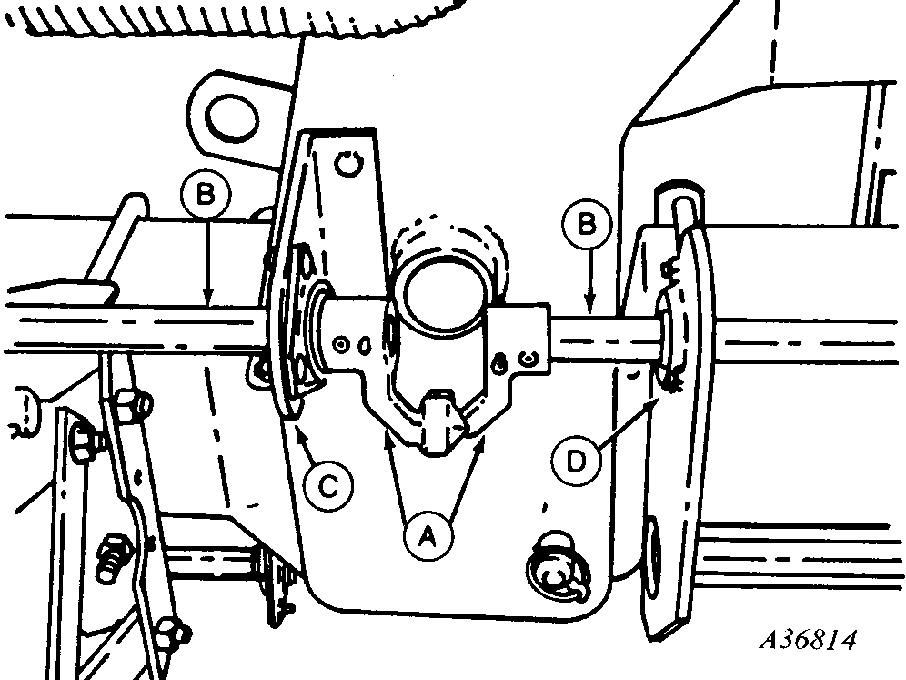
4.
Remove countershaft drive couplers (A) from both right- and left-hand sides of planter.
NOTE:
Drive chains should be removed from wing-wheel modules if planter will not be converted back to rigid operation.
|
|
|
5.
Install wing lock-down pin (A) above each lift arm to prevent the entire wing section from moving straight up or down.
Remove pin (B) to allow the wings to flex up and down approximately 5 degrees.
Optional hydraulic method of locking wings instead of installing wing lock-down pins at (A) as described in step 5, use a lever lock clip over the tractor selective control valve lever float lock-out stop to keep the fold cylinders extended while planting.
|
|
|