Replacing Seed-Opener Blades and Seed-Tube GuardOpener blades should be replaced if beveled edge is worn off or diameter is below specification, whichever appears first. Specification
If opener blades must be replaced for any reason, be certain they are replaced with correct amount of blade contact. To replace blades, proceed as follows: |
AG,OUO6074,1368 -19-04AUG00-1/7 |
|
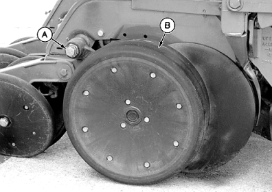
1. Remove cap screw (A) and gauge wheel (B) from pivot shaft.
|
|
AG,OUO6074,1368 -19-04AUG00-2/7 |
|
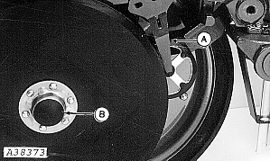
2. Planting unit equipped with rotary scraper-Pull front engagement pin outward, disengage scraper assembly from shank panels, rotate and insert scraper (A) between opener blades. 3. Remove hub cap (B).
|
|
AG,OUO6074,1368 -19-04AUG00-3/7 |
|
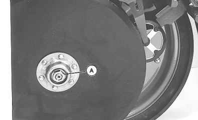
NOTE: Nut on left-hand side of opener has left-hand threads. 4. Remove nut and washer (A) from outside of bearing.
|
|
 CAUTION:
Disk blades are sharp. Wear protective gloves and handle disks carefully to avoid being injured.
CAUTION:
Disk blades are sharp. Wear protective gloves and handle disks carefully to avoid being injured.
AG,OUO6074,1368 -19-04AUG00-4/7 |
|
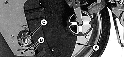
5. Remove disk blade (A) and hardened washers (C) from shaft. If seed-tube guard is excessively worn, replace by removing pins (B) and guard. Install new guard and pins.
|
|
AG,OUO6074,1368 -19-04AUG00-5/7 |
|
IMPORTANT: To properly install blade assembly (A), add or remove hardened washers behind blade bearing to obtain 38 mm to 64 mm (1.5 in. to 2.5 in.) of blade edge contact at leading edge when nut is tightened. Washers not placed behind blade bearing should be placed on front side of blade bearing. Inserting two pieces of paper between disks on each side of contact points on leading edge will help verify this dimension. NOTE: Nut on left-hand side of opener has left-hand threads. 6. Replace blade, bearing washers, and nut. Tighten nut (A) to specification. Specification
When assembled, blades should turn with minimal resistance. |
|
AG,OUO6074,1368 -19-04AUG00-6/7 |
|
7. Install disk scrapers (A), cap (B) and gauge wheels to complete procedure. See ADJUSTING GAUGE WHEELS in this section.
|
|
AG,OUO6074,1368 -19-04AUG00-7/7 |