Attaching Machine to Tractor
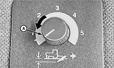
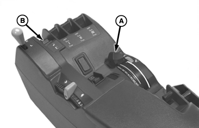
Place the hitch load/depth control (A) in "position" setting for better control when hitching and during operation.
|
|
 CAUTION:
Do not stand between tractor and machine unless the tractor transmission is in PARK.
CAUTION:
Do not stand between tractor and machine unless the tractor transmission is in PARK.
OUO6074,0000193 -19-19JAN01-1/6 |
|
Raise both latch control levers. |
|
OUO6074,0000193 -19-19JAN01-2/6 |
|
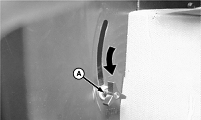
Lower rockshaft using hitch control lever (A) until the quick-coupler hooks are lower than the machine hitch pins and slowly back the tractor up to the machine. Check drawbar clearance. If drawbar contacts coupler or machine, turn drawbar offset down and in shortest possible position.
Raise the rockshaft using hitch control lever (A) enough to engage the machine hitch pins in the quick-coupler hooks. Push both latch control levers down to lock the machine to the quick-coupler.
|
|

OUO6074,0000193 -19-19JAN01-3/6 |
|
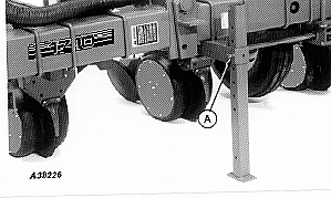
NOTE: Check tractor dual wheel tire clearance. After machine is attached to tractor, remove spring locking pin and drilled pin (A). Install stand in raised position with drilled pin and spring locking pin. IMPORTANT: To prevent damage to planting units, remove parking straps after connecting machine to tractor. Remove parking straps (if equipped) from outside planting units, when lift assist wheels are NOT installed, after connecting machine to tractor.
|
|
OUO6074,0000193 -19-19JAN01-4/6 |
|
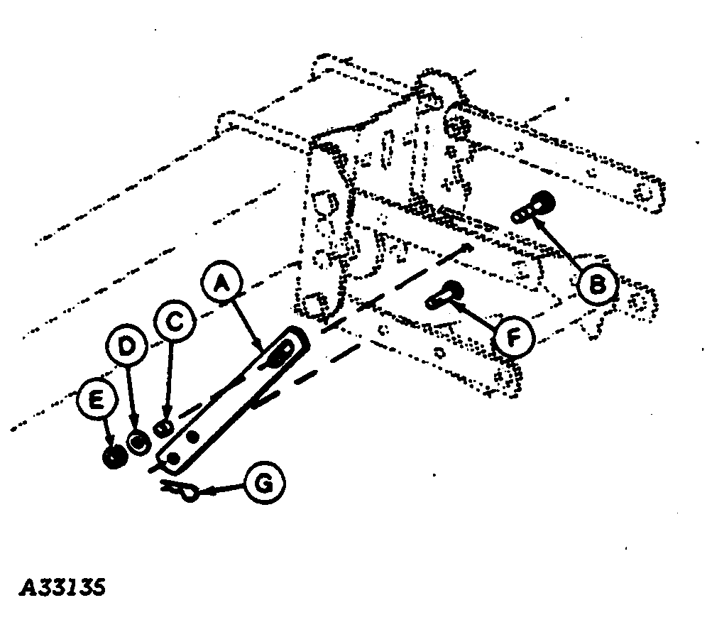
Remove drilled pin (F) and spring locking pin (G) to remove strap from lower parallel arm. Remove M12 x 45 cap screw (B), bushing (C), flat washer (D) and nut (E) to remove strap (A) from upper parallel.
|
|
OUO6074,0000193 -19-19JAN01-5/6 |
|
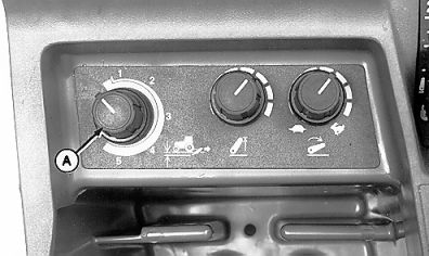
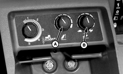
Adjust height limit by turning control knob (A). Turning knob fully counterclockwise will limit height to 25 percent of maximum. Turning knob full clockwise will allow maximum height. Adjust rate of drop by turning control knob (B). Turning knob clockwise will increase drop rate and turning it counterclockwise will decrease drop rate.
|
|

OUO6074,0000193 -19-19JAN01-6/6 |