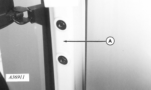
Install GREENSTAR™ Display-8000 and 9000 Series Tractors1. Unscrew plastic covers from right-hand front post (A) to remove. (Already removed in illustration.)
|
|
|
GREENSTAR is a trademark of Deere & Company. | AG,OUO6023,986 -19-21JUL00-1/10 |
|
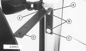
2. Install "L" bracket (A) on front post with two M10 x 20 cap screws (B) with flat washer (C) on lower cap screw. 3. Install monitor strap (D) with M10 x 30 hex head bolt and wing nut (E), with strap hole spacing as shown.
|
|
AG,OUO6023,986 -19-21JUL00-2/10 |
|
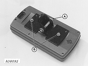
4. Attach monitor bracket to pivot with M10 x 60 cap screw and nut (A). 5. Attach bracket to monitor with two M6 x 16 cap screws (B). 6. Install monitor to mounting bracket with M6 x 20 cap screw and nut (C) making certain to install rubber washer on top of strap.
|
|
AG,OUO6023,986 -19-21JUL00-3/10 |
|
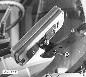
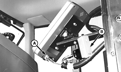
7. Install monitor harness (A) into monitor. 8. Fasten terminator (B) to underside of mounting bracket with tie strap.
|
|
AG,OUO6023,986 -19-21JUL00-4/10 |
|
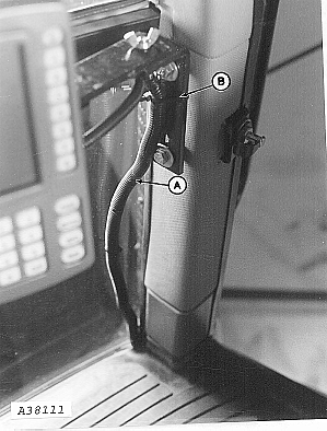
9. Route harness (A) down side of cab and under floor mat, along right-hand console. 10. Fasten with tie straps (B).
|
|
AG,OUO6023,986 -19-21JUL00-5/10 |
|
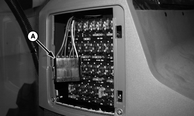
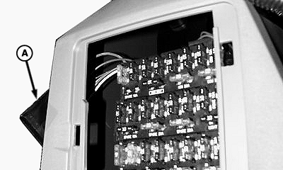
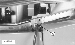
11. Remove fuse panel cover and locate 6-pin harness connector (A).
|
|
AG,OUO6023,986 -19-21JUL00-6/10 |
|
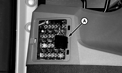
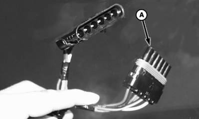
12. Push 6-pin harness (A) out between fuse panel and window.
|
|
AG,OUO6023,986 -19-21JUL00-7/10 |
|
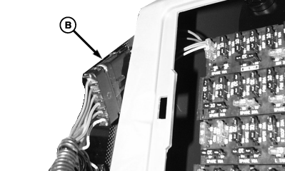
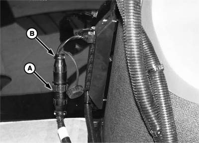
13. Separate 6-pin connector (A) on monitor harness and connect to 6-pin connector (B) from fuse panel.
|
|
AG,OUO6023,986 -19-21JUL00-8/10 |
|
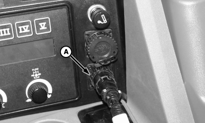
14. Install controller power harness (A) into rear outlet or into front convenience outlet using adapter harness (B), if equipped. 15. Route harness under floor mat.
|
|
AG,OUO6023,986 -19-21JUL00-9/10 |
|
16. Remove existing right-hand side grommet. Install harness in new grommet (provided) and install grommet (A) as illustrated.
|
|
AG,OUO6023,986 -19-21JUL00-10/10 |