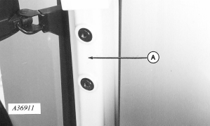
Installing GREENSTAR® Display (8000, 8010, 8020, 9000, 9010, 9020 Series Tractors with out GREENSTAR® Ready Option)Bracket Installation1. Remove plastic covers from right-hand front post (A) to remove. (Already removed in illustration.)
|
|
|
GREENSTAR is a trademark of Deere & Company. | AG,OUO1074,1614 -19-24APR00-1/14 |
|
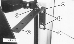
2. Install L-bracket (A) on front post with two M10 x 20 cap screws (B) with flat washer (C) on lower cap screw. 3. Install monitor strap (D) with M10 x 30 hex head bolt and wing nut (E), with strap hole spacing as shown.
|
|
AG,OUO1074,1614 -19-24APR00-2/14 |
|
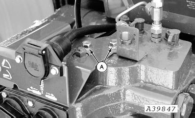
4. Remove two cap screws (A) and discard.
|
|
AG,OUO1074,1614 -19-24APR00-3/14 |
|
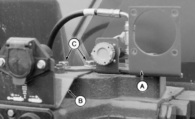
5. Install monitor bracket (A) on top of 7-pin bracket (B) and fasten with M12 x 20 cap screws (C).
|
|
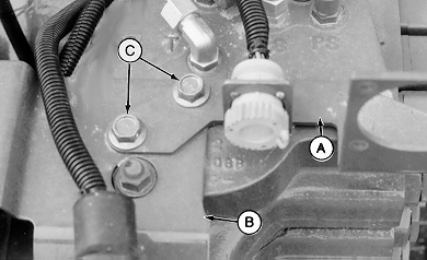
AG,OUO1074,1614 -19-24APR00-4/14 |
|
Monitor Installation
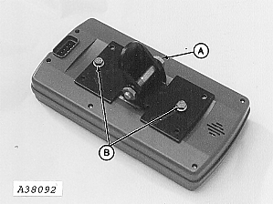
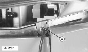
1. Attach monitor bracket to pivot with M10 x 60 cap screw and nut (A). NOTE: M6 x 12 cap screws are inside packing of display box. 2. Attach bracket to monitor with two M6 x 12 cap screws (B). 3. Install monitor to mounting bracket with M6 x 20 cap screw (C) making certain to install rubber washer on top of strap.
|
|
AG,OUO1074,1614 -19-24APR00-5/14 |
|
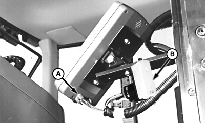
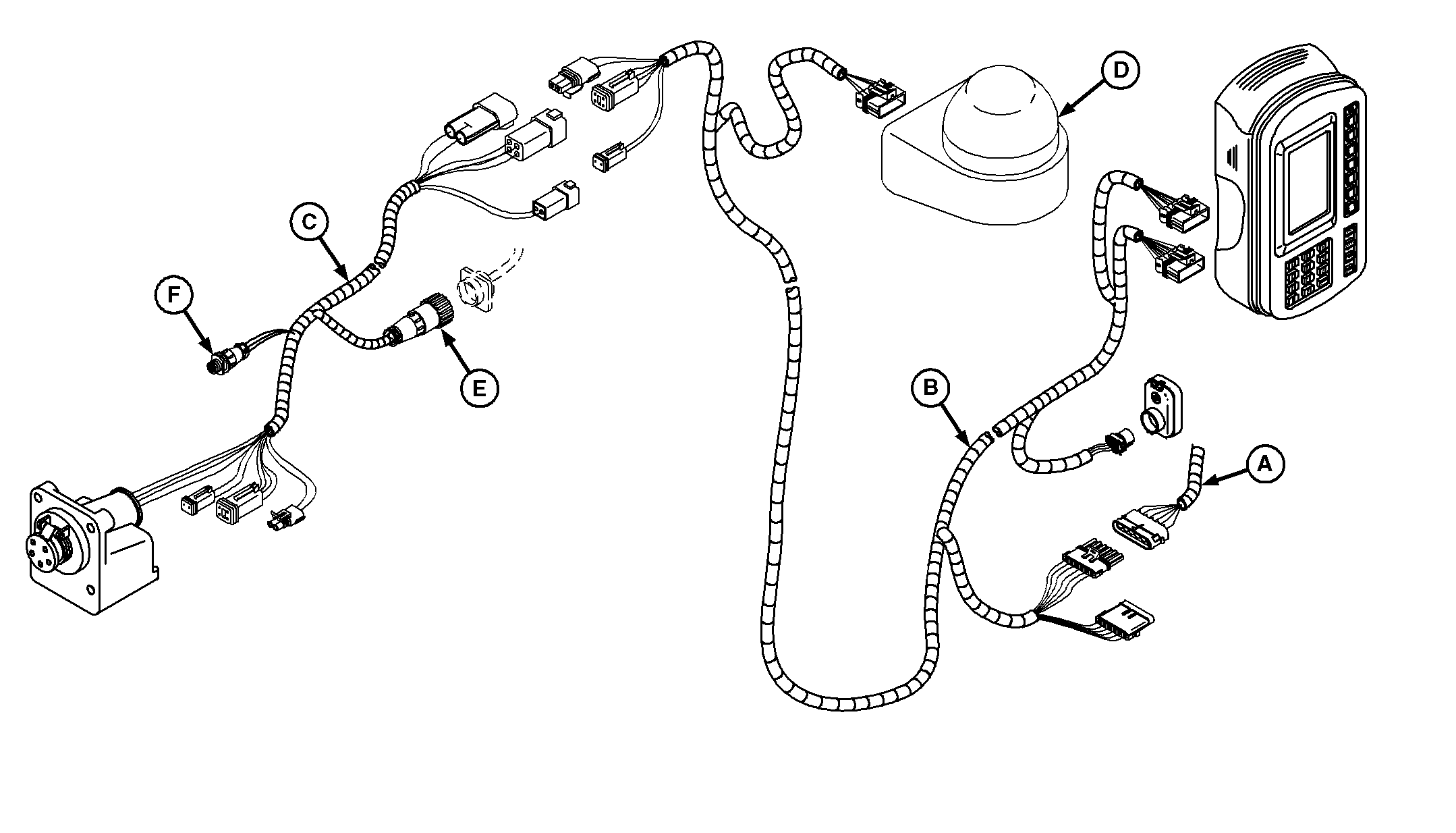
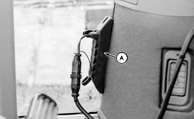
4. Install cab harness (A) into monitor. 5. Fasten terminator (B) to underside of mounting bracket with tie strap.
|
|
AG,OUO1074,1614 -19-24APR00-6/14 |
|
|
|
|
|
|
Electrical Power Requirements
NOTE: The GREENSTAR ® Harness requires two different power sources. One is used to power the Display, Mobile Processor and GPS |
Receiver, the other to power the implement devices. These power sources are the convenience outlet and the program connector. |
|
GREENSTAR is a trademark of Deere & Company. | AG,OUO1074,1614 -19-24APR00-7/14 |
|
GREENSTAR
®
Harness Routing
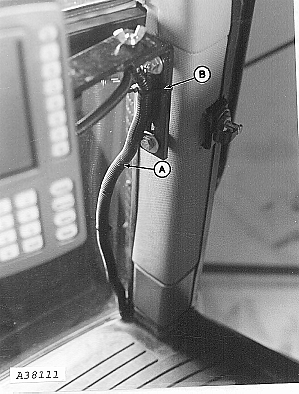
1. Route harness (A) down side of cab and on top of floor mat along right-hand console. 2. Fasten with tie straps (B).
|
|
|
GREENSTAR is a trademark of Deere & Company. | AG,OUO1074,1614 -19-24APR00-8/14 |
|
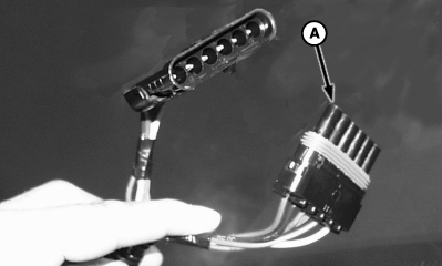
3. Separate 6-pin connector (A) on cab harness and connect to 6-pin diagnostic connector (B) on tractor. 4. Connect implement harness to cab harness. |
|
AG,OUO1074,1614 -19-24APR00-9/14 |
|
5. Connect implement harness into auxiliary power strip (A) or rear convenience outlet (B).
|
|
AG,OUO1074,1614 -19-24APR00-10/14 |
|
6. Remove existing right-hand side grommet. Install harness in new grommet (provided) and install grommet (A).
|
|
AG,OUO1074,1614 -19-24APR00-11/14 |
|
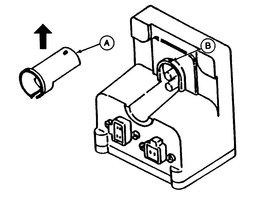
NOTE: Cover (A) for 4-pin connector can be removed to simplify connection of red and black wires to terminals. 7. To remove cover, lift rear portion to remove from pin (B), then lift straight up in direction of arrow.
|
|
AG,OUO1074,1614 -19-24APR00-12/14 |
|
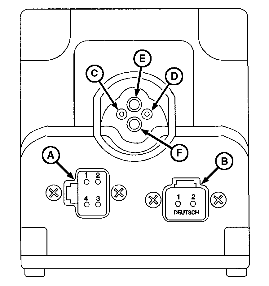
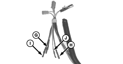
8. Connect 4-pin plug on implement harness to connector (A) and 2-pin plug to connector (B). 9. The ISO Implement connector must have the 2 red and 2 black wires connected to the top four sockets. These wires come tucked behind the protective wire conduit. 10. Cut the tape wrapped around these wires and remove the shrink-wrap. NOTE: Positive and negative symbols are molded into the lip of the box as a guide showing where the insert wires. NOTE: To connect wires, insert wire end firmly into terminal. Properly connected wire will remain connected when wire is gently pulled. 11. Connect large red wire (G) to terminal (E), small black (H) to terminal (D), large black (I ) to terminal (F) and small red (J) to terminal (C).
|
|
AG,OUO1074,1614 -19-24APR00-13/14 |
|
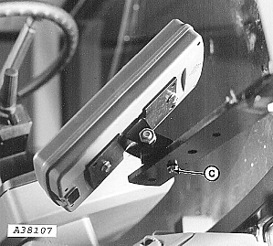
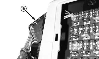
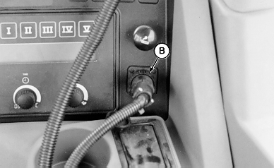
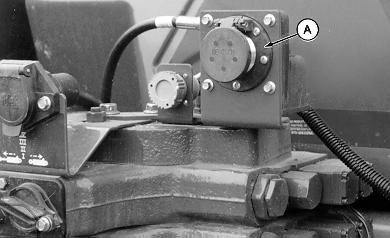
12. Attach monitor connector (A) to bracket with M6 x 16 cap screws.
|
|
AG,OUO1074,1614 -19-24APR00-14/14 |