Installing AgitatorsAgitators (A) need to be installed above each active meter inlet opening ONLY to keep product free flowing. Agitators found above inactive meter segments should be deactivated by pulling spring locking pins (B). Meter housing need not be removed to service agitators; however, tank will need to be empty. Installing agitators is a two-person job, one person outside the tank to slide shaft from housing and one person inside tank to position and install agitators and hair pins. |
|
OUO6030,00015CB -19-08MAR01-1/6 |
|
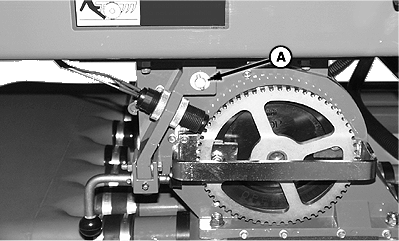
1. To service agitators: Outside Person: Disconnect drive arm (A) from agitator shaft crank (B). 2. Remove hardware and crank arm from shaft. Remove and retain flat washers from shaft end.
|
|
OUO6030,00015CB -19-08MAR01-2/6 |
|
3. Inside Person: Remove all existing Spring Locking Pins (A) from shaft. NOTE: Meter housing shown removed from cart for clarity.
|
|
 CAUTION:
Do not enter tank unless another person is present and hydraulic hoses are disconnected from tractor.
CAUTION:
Do not enter tank unless another person is present and hydraulic hoses are disconnected from tractor.
OUO6030,00015CB -19-08MAR01-3/6 |
|
4. Outside Person: Pull agitator shaft (A) from left-hand meter end cap. NOTE: Half-width disconnect decal plate is installed on agitator shaft. Plate will come free when shaft is removed. 5. Inside Person: Collect existing agitators as shaft is removed.
|
|
OUO6030,00015CB -19-08MAR01-4/6 |
|
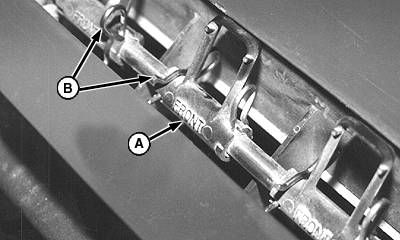
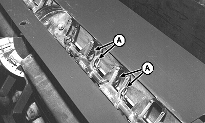
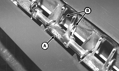
6. Outside Person: Slide agitator shaft back into bore through left-hand end cap and half-width disconnect valve. 7. Inside Person: Position agitators (A) so "FRONT" is to the front-side of the cart. Place agitators on shaft as it is installed. Install needed number of agitators on left-hand end of shaft before it passes through the middle support block and half-width decal plate. Then install needed number of agitators on right-hand side of center. Be sure to install same number of agitators as active meter segments, putting one above each active meter segment (between raised ribs of the half-width disconnect valves). 8. Slide agitators over top of active meter segments and retain with two Spring Locking Pins (B). |
|
OUO6030,00015CB -19-08MAR01-5/6 |
|
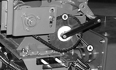
9. Outside Person: Return flat washers to shaft end, and install crank arm (B) with hardware. 10. Attach drive arm (A) to crank.
|
|
OUO6030,00015CB -19-08MAR01-6/6 |