Changing Input Sprocket Combinations
1.
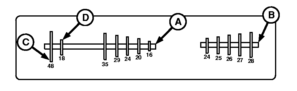
Consult planting rate chart to determine desired sprocket combinations.
A-Rear Shaft (Driver)
B-Front Shaft (Driven)
C-Low Range
D-High Range
|
Number of Sprocket Teeth
|
|
|
OUO1074,00001B6 -19-12APR05-1/5
|
|
2.
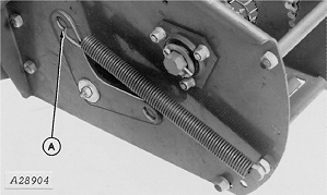
Remove spring (A) from chain tightener.
A-Spring
|
|
|
|
OUO1074,00001B6 -19-12APR05-2/5
|
|
3.
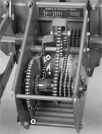
Remove required number of rubber sprocket spacers (A).
4.
Remove chain (B) from input sprocket.
A-Rubber Sprocket Spacers
B-Chain
|
|
|
|
OUO1074,00001B6 -19-12APR05-3/5
|
|
5.
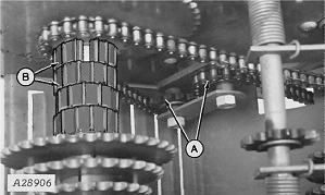
Align desired input sprocket with chain tightener sprockets (A).
6.
Install chain on sprocket and rubber sprocket spacers (B) on shaft.
A-Sprockets
B-Rubber Sprocket Spacers
|
|
|
|
OUO1074,00001B6 -19-12APR05-4/5
|
|
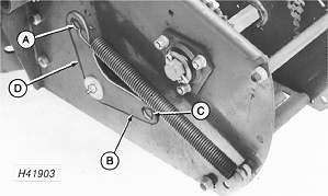
7.
If chain is aligned on high-range input sprocket, locate spring in hole (A) of chain tightener. Arm (B) must point rearward.
8.
If chain is installed on low-range input sprocket, locate spring in hole (C) of chain tightener. Arm (D) must point forward.
A-Hole
B-Arm
C-Hole
D-Arm
|
|
|
|
OUO1074,00001B6 -19-12APR05-5/5
|
|