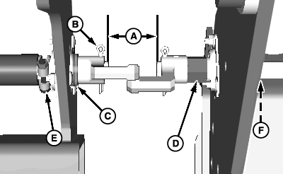
Align Jackshaft Couplers-Split-Row Machine1. Unfold machine, completely lower to ground and pull forward slightly to engage drives.2. If drive coupler flats do not align as shown, proceed as follows. a. Measure distance (A) between driveshaft ends. b. If drillshaft separation is not within specification, remove cotter pin (B). Specification
c. Loosen clamp (E) to allow positioning of drillshaft as needed. d. Add or remove washers (C), as needed, until drive couplers are within specifications. e. Install cotter pin. f. Push coupler toward bearing to remove end play, then reposition clamp (E) against bearing and tighten to hold drillshaft in place. g. Verify dimension is as specified. Repeat Steps (C-F) until dimension is correct. If proper separation cannot be achieved, remove spacer (D) and replaced with two 28H3409 spacers. two 24M7091 washers and two 24H1465 washers. This provides a greater range of adjustment. h. Loosen clamp (F) to reposition shaft as needed after spacers and washers have been installed. |
|
OUO6045,000076F -19-23JUL07-1/2 |
|
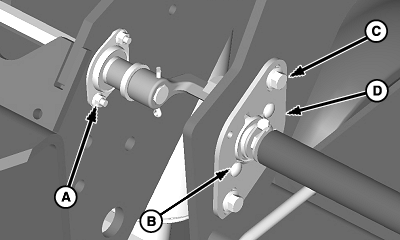
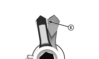
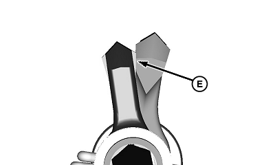
NOTE: If shaft is difficult to rotate, remove chains. 3. Rotate drive couplers by hand and observe alignment of flat surfaces (E). If surfaces remain within 3 mm (1/8 in.) throughout full rotation, couplers are aligned properly. If alignment exceeds 3 mm (1/8 in.), adjust as follows: NOTE: If more room is needed for adjustment, loosen mounting hardware on additional bearing flanges along length of drillshaft. a. Loosen round head bolts and nuts (A and B) on bearing flanges. b. Loosen cap screws and nuts (C) on bearing adjustment bracket (D). c. Adjust drillshaft position as required to align flat surfaces of drive couplers as shown. d. Tighten all bearing and bracket hardware. e. Rotate drillshaft one complete revolution and verify couplers maintain alignment throughout entire rotation.
|
|
OUO6045,000076F -19-23JUL07-2/2 |