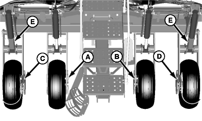
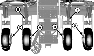
Adjust Frame Height-Center FrameIMPORTANT: Perform all frame height adjustments with machine on level ground. Center frame wheel pairs must be adjusted to the same settings. NOTE: Soil conditions can affect frame height. Wing wheels can be adjusted differently than the center frame wheels due to varying attachments and frame configurations. NOTE: Adjust center frame wheel modules in pairs. 1. To change frame height on wheel modules (A) and (B), do the following:
2. To change frame height on wheel modules (C) and (D), do the following:
|
|
OUO6435,0001ECF -19-25JUN08-1/2 |
|
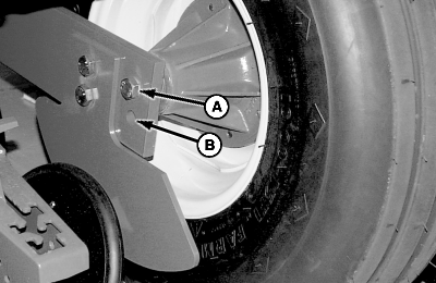
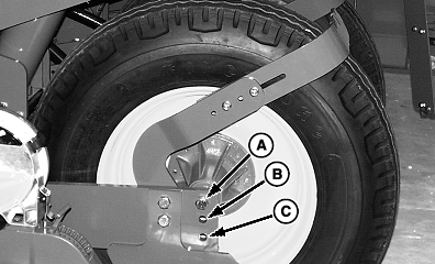
IMPORTANT: All four center frame wheels must be set in the same position. 3. Position wheel hubs so bottom of center frame is 510-560 mm (20-22 in.) above the ground. Location (A) is for normal conditions. Location (B) raises frame two inches and is used for softer soil conditions. 24 Row: Location (C) is for soft soil conditions. 4. Tighten wheel hub cap screws to specification after making adjustments. Specification
5. Repeat for adjacent wheel.
|
|
OUO6435,0001ECF -19-25JUN08-2/2 |