Install Monitor Sensors—1560, 1590
-
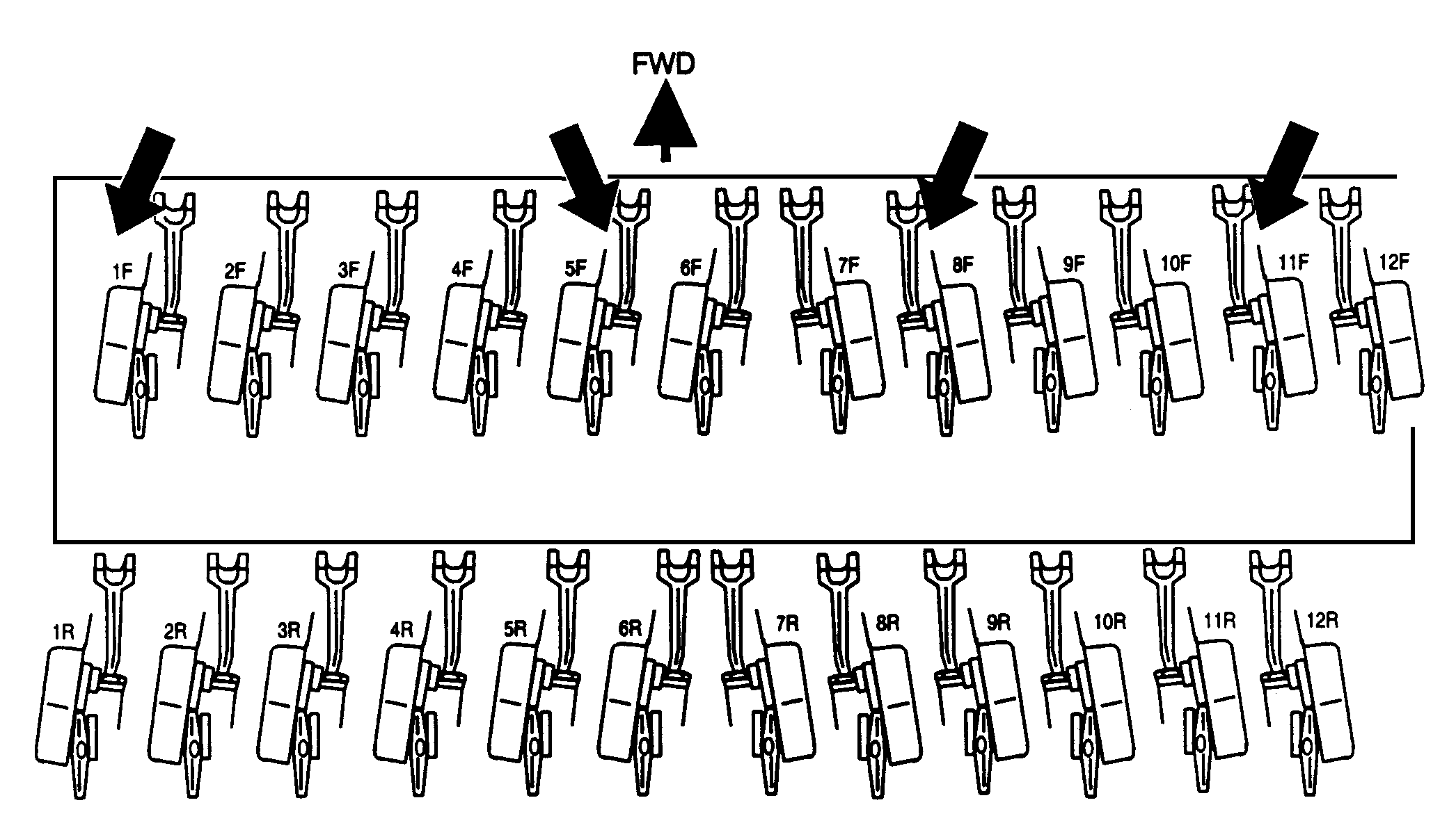
A45193-UN-18NOV9824—Row 4.57 m (15 ft.) Shown
Remove seed tube hose from feed cup and convolute tube. See the following table for proper hoses to remove.1560/1590 Drill
Drill Width
Row Spacing
Row Numbers
16 Row
3048 mm (120 in.)
191 mm (7.5 in.)
1F, 4F, 6F, 8F
18 Row
4572 mm 180 in.)
254 mm (10 in.)
1F, 4F, 6F, 9F
24 Row
4572 mm 180 in.)
191 mm (7.5 in.)
1F, 5F, 8F, 11F
32 Row
6096 mm (240 in.)
191 mm (7.5 in.)
1F, 6F, 10F, 15F
NOTE: If front rank lockup is used, install sensors on rows 1R, 5R, 8R, 11R, on a 4.57 m (15 ft.) machine with 191 mm (7.5 in.) spacing.
-
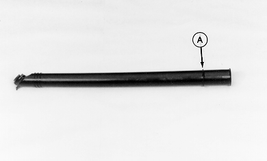
A45194-UN-16NOV98A - Rib
Cut tube just over rib (A) on lower end of tube. Clean rough edges. -
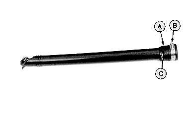
A45195-UN-16NOV98A - Clamp Halves
B - Hose Clamp
C - Holes
Assemble clamp halves (A) with hose clamp (B). -
Insert tube to stops inside clamp halves.
-
Drill holes (C) in seed tube using holes in clamp halves as template.
-
Disassemble clamp halves.
-
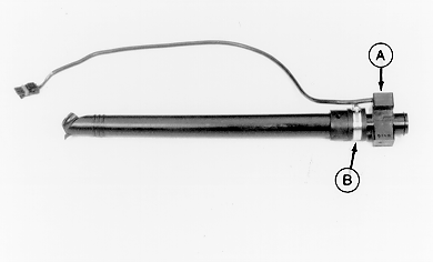
A45196-UN-16NOV98A - Sensor
B - Hose Clamp
Assemble tube and sensor (A) in one clamp half. Nub on clamp half fits in drilled hole in seed tube. Place rib on sensor in groove of clamp. -
Position other half of clamp and fasten with hose clamp (B).
-
Repeat steps 2—8 for other three seed tubes.
-
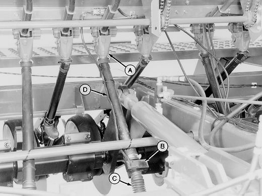
A45197-UN-16NOV98A - Feed Cup
B - Sensor
C - Convolute Tube
D - Sensor Harness
Install seed tubes to specified rows and attach to feed cups (A). -
Insert bottom of sensor (B) into convoluted tube (C). Make sure to insert flange of sensor into third rib of convoluted tube.
-
Route sensor harness (D) up seed tubes and secure with tie bands.
|
OUO6045,00000EE-19-20090209 |