Calibrate Hydraulic Drive Motor Valve
NOTE: Perform Bleed Procedure before Calibration Procedure after any system repairs.
Calibrating VRD motors is required after repairs are made to any hydraulic drive motor or valve.
-
Start tractor. Run engine at slow idle and run air cart fan until hydraulic oil reaches minimum temperature of 21° C (70° F).
-
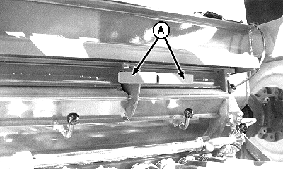
A41536-UN-10APR97A - Half-Width Disconnect Handles
Meters That Are Being Calibrated: Push both half-width disconnect handles (A) up to stop product flow. -
Access Hydraulic Maintenance by using Quick Select Button J to navigate to Diagnostics and Test screen.
-
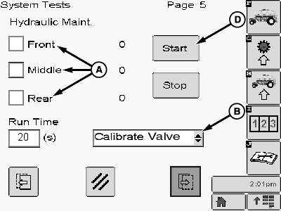
A73557-UN-15NOV11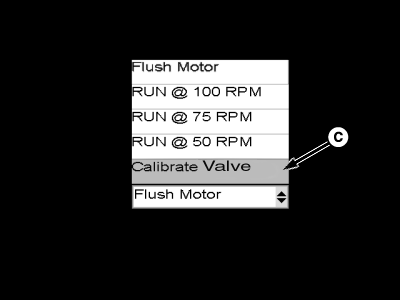
A73556-UN-16NOV11A - Motor Selection
B - Drop-down List
C - Motor Speed Selection, Calibrate Valve
D - Start
Select a motor check box (A) to run that motor. -
Select drop-down (B) and set to calibrate valve (C).
-
Select Start button (D).
-
Motor runs at calibration speed.
-
If motor speed readout on monitor is not 115 to 125 rpm, calibration is needed.
-
IMPORTANT: A 2 mm hex screw is located inside the 6 mm adjustment screw (D). Do not loosen or use smaller screw during calibration procedure.
NOTE: Use a person to view and report on the monitor display readings and a person at the meter to make the actual adjustment.
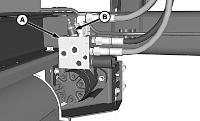
A73489-UN-03NOV11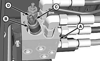
A73490-UN-03NOV11A - Valve Block
B - Adjustment Valve
C - Jam Nut
D - Adjustment Screw, 6 mm
Locate valve block (A) and valve (B) for selected meter. -
Loosen jam nut (C) on valve.
-
NOTE: To increase motor speed, turn adjustment screw clockwise.
Using a 6 mm hex key wrench, turn adjustment screw (D) until motor speed is 115 to 125 rpm on display.
-
Tighten jam nut and verify that speed is still 115 to 125 rpm.
-
Repeat for each motor as needed.
|
LD45720,0000511-19-20111213 |