Information Signs
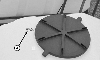
A74097-UN-26JAN12
A - Decal, Lid Index
To align threads, position a handle here before screwing lid into tank.(See OPERATING TANK LIDS in Central Commodity System section.)
IMPORTANT:
A72425-UN-01SEP11
A - Decal, Vacuum Sensor
Avoid sensor damage. Do not directly spray the sensor with a pressure washer. Do not apply compressed air to sensor lines while connected to sensors.(See REMOVING FROM STORAGE and STORING MACHINE in Storage section.)
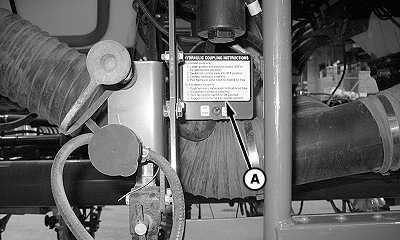
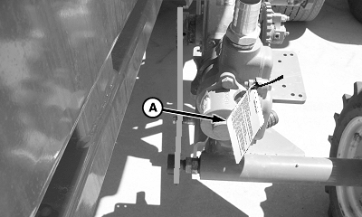
A74117-UN-27JAN12
A - Decal, Hydraulic Coupling Instruction
TO CONNECT COUPLERS: 1. Lower the planter and move tractor SCV lever to forward detent position (continuous flow). 2. Move the fan control switch to Off position. 3. Connect hydraulic couplers. 4. Pull knob on valve to enable oil flow.TO DISCONNECT COUPLERS: 1. Push knob on valve to disable oil flow. 2. Disconnect hydraulic couplers. 3. Move the fan control switch to On position. 4. Move tractor SCV lever to neutral position.
(See AUXILIARY HYDRAULIC ATTACHMENT OPERATION in General Attachments section.)
A74148-UN-30JAN12
A - Decal, Fertilizer Pump
IMPORTANT:LUBRICATION (See Lubrication section.)
- Fill pump lube fittings with multipurpose grease every 10 hours of operation.
- Check oil level at initial start-up and then daily.
-
Single piston pump: Fill with TV6296 SAE 80/90 W EP gear oil
or equivalent to the oil port level.
Double piston pump: Fill both cavities with non-detergent SAE 30 oil to the check plug level.
PREVENT DAMAGE TO PUMP (See Storage section.)
- Keep pump filled with fluid at all times.
- Remove drive chain when not in use.
- Protect from freezing (see storage information below).
Overnight Storage In Above Freezing Temperatures:
- Using a clear fertilizer solution with steady or rising temperatures: Acceptable to leave pump and hoses filled.
- Using a clear fertilizer solution with falling temperatures (solution may separate): Fill pump with water and leave filled (do not admit air into system).
- Suspension fertilizer: This system not recommended for use with suspension fertilizers.
Extended Storage (Over 1 Week) Including Winter Storage: Refer to frame decal and operators manual.
IMPORTANT:
PUMP PRIMING (See Liquid Fertilizer System section.)
-
Open shutoff valve at tank and strainer.
-
Fill tank with a minimum of 75 L (20 gal.) and check system for leaks
-
IMPORTANT: Avoid excessive system pressure. Do not exceed maximum recommended rate for orifice or nozzle size.
Refer to rate chart and set pump to maximum rate for the in-line orifice or nozzle that is installed.
-
Lower machine to planting position and drive 90 meters (100 yards) at planting speed 9.7 km/h (6 mph.).
-
Raise machine and turn fertilizer pump drive wheel by hand.
-
Check all rows for liquid exiting the opener tubes in a steady stream. Repeat steps 2—5 until a steady flow of liquid is apparent at all openers and all air is flushed from distribution hoses.
-
Select a target fertilizer rate from rate chart. Set pump range and install in-line orifices or nozzles for selected fertilizer rate.
-
NOTE: As travel speed increases, the fertilizer system pressure also increases.
Verify that system pressure is within 103—621 kPa (1.0—6.2 bar) (15—90 psi) when traveling at desired planting speed.
-
If machine is stationary for a long period, air bubbles can develop and become trapped in the distribution hoses. Prime system as necessary.
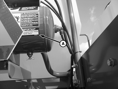
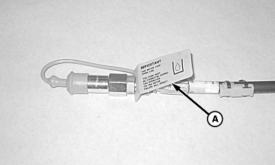
A74120-UN-27JAN12
A - Decal, Air Tank Drain
IMPORTANTDrain moisture from air tank daily.
(See DRAIN AIR STORAGE TANK in Integrated Pneumatic Down Force section in your SeedStar Monitor Manual.)
A71439-UN-11MAY11
A - Decal, Case Drain
IMPORTANTFAN MOTOR CASE DRAIN LINE.
This hose must be connected during fan operating to avoid fan motor failure.
(See LOW PRESSURE CASE DRAIN CONNECTION in Prepare Tractor section.)
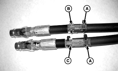
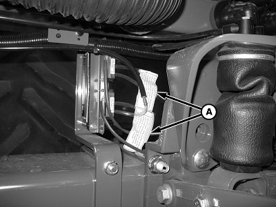
A71412-UN-05MAY11
A - SCV Number
B - Flow Direction
C - Flow Direction
Identification tags are installed on end of hydraulic hoses. The symbols match valve identification on rear of tractor.(A) Identifies tractor SCV circuit.
(B and C) Identify the direction of oil flow.
|
OUO6064,000060D-19-20120621 |