Adjust Frame Height (Non CCS Machines Only)
NOTE: During operation, parallel arms must be parallel to the ground or angled slightly upward toward frame.
NOTE: If machine is equipped with variable rate drive, the gauge wheel with the motion sensor is designed to float and uses a separate adjustment procedure.
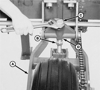
A48817-UN-27FEB02
A - Drive Gauge Wheels
B - Jam Nut
C - Cap Screw
D - Casting
IF EQUIPPED WITH MECHANICAL DRIVE: Adjust drive-gauge wheels (A) until machine frame is 510—560 mm (20—22 in.) above the ground.-
Loosen jam nut (B).
-
Turn cap screw (C) clockwise to raise wheel and lower machine frame.
-
Turn cap screw (C) counterclockwise to lower wheel and raise machine frame.
-
Tighten jam nut (B) against casting (D) to prevent cap screw (C) rotation.
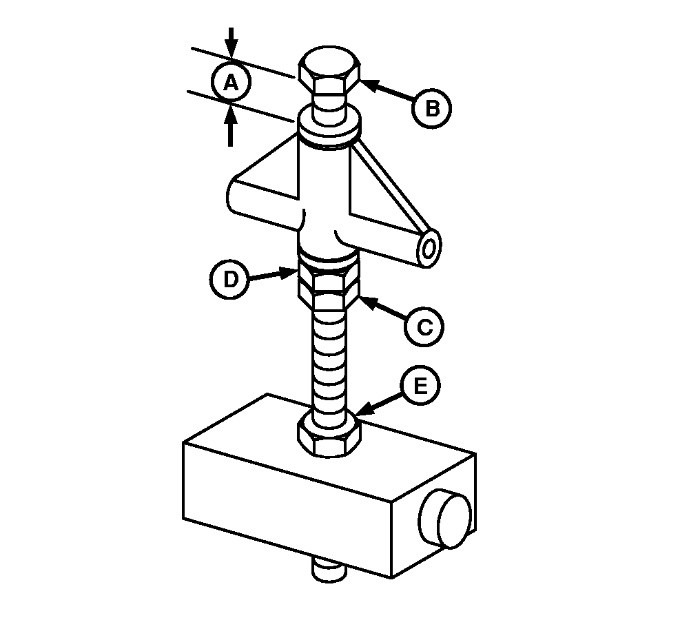
A48818-UN-04MAR02
Floating Drive-Gauge Wheels
A - Dimension
B - Cap Screw
C - Jam Nut
D - Nut
E - Jam Nut
IF EQUIPPED WITH VARIABLE RATE DRIVE: Adjust floating drive-gauge wheel (wheel with motion sensor installed) as follows:-
NOTE: Dimension (A) is measured between bottom of cap screw (B) head and top of washer.
Loosen jam nut (C).
-
NOTE: In uneven terrain conditions, set dimension (A) to 70 mm (2-3/4 in.).
Adjust nut (D) until dimension (A) is 51 mm (2 in.) for normal terrain conditions.
-
Tighten jam nut (C).
-
Loosen jam nut (E).
-
Adjust cap screw (B) until frame height is 510—560 mm (20—22 in.) above the ground.
-
Tighten jam nut (E) against lower casting.
|
OUO6045,0000182-19-20090624 |