Adjust Center Frame Height
IMPORTANT: Perform all frame height adjustments with machine on level ground.
Center frame wheel pairs must be adjusted to the same settings.
NOTE: Soil conditions affect frame height. Wing wheels can be adjusted differently than the center frame wheels due to varying attachments and frame configurations.
-
NOTE: Adjust center frame wheel modules in pairs.
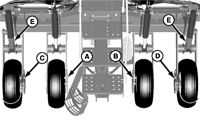
A51274-UN-26NOV02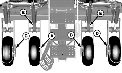
A51275-UN-26NOV02A - Wheel Module
B - Wheel Module
C - Wheel Module
D - Wheel Module
E - Service Locks
To change frame height on wheel modules (A) and (B):- Install service locks (E) on wheel modules (C) and (D).
- Lower machine onto service locks until pressure is removed from wheels being adjusted.
-
To change frame height on wheel modules (C) and (D):
- Install service locks (E) on wheel modules (A) and (B).
- Lower machine onto service locks until pressure is removed from wheels being adjusted.
-
IMPORTANT: All four center frame wheels must be set in the same position.
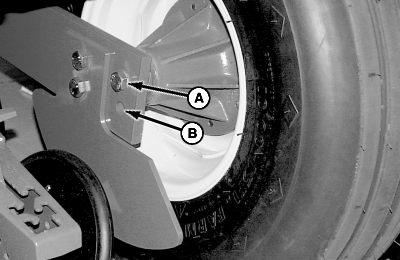
A51276-UN-26NOV0212/16 Row
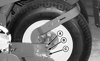
A53354-UN-01DEC0324 Row
A - Wheel Hub Location (Normal Conditions)
B - Wheel Hub Location (Raise Frame)
C - Wheel Hub Location (Soft Soil Conditions)
Position wheel hubs so bottom of center frame is 510—560 mm (20—22 in.) off ground. Location (A) is for normal conditions. Location (B) raises frame two inches and is used for softer soil conditions.24 Row: Location (C) is for soft soil conditions.
-
Tighten wheel hub cap screws to specification after making adjustments.
Item Measurement Specification Center Frame Wheel Cap Screws Torque 610 N·m (450 lb.-ft.) -
Repeat for adjacent wheel.
|
OUO6435,0001ECF-19-20090521 |