Operate Wireless Conveyance System
-
A73111-UN-17OCT11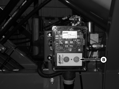
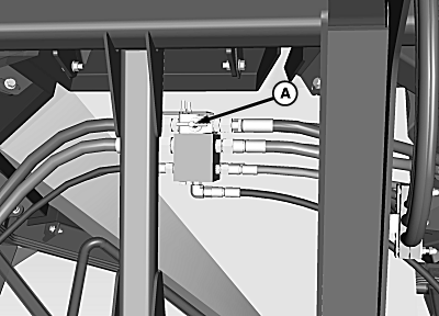
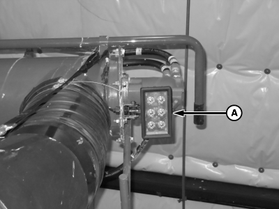
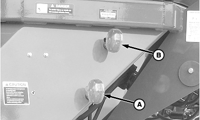
A82210-UN-03APR14A - Fan/Auger Selector Valve
B - Receiver Power On Button
Set selector valve (A) to auger/conveyor position. -
Turn on the conveyance receiver by pressing the power-on button (B).
-
Turn on the remote by pressing the power-on button for the desired remote.
-
NOTE: Hydraulic cylinders function only while remote button is pressed. For best results, hold function button down when using the conveyance system.
Press function buttons on remote to operate hydraulic conveyance system.
-
 CAUTION:
Avoid sudden upward movement of lid. Stop fan before tank lid is opened.
TS220-UN-15APR13Avoid exposure to airborne chemicals. If tank lid is opened while tank is pressurized, dust and fumes are exhausted.
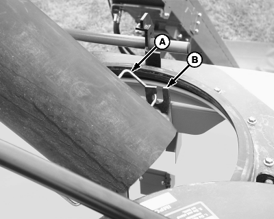
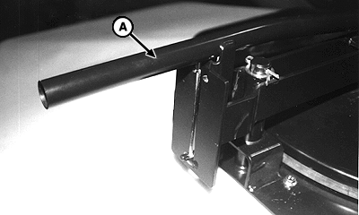
A49399-UN-13MAY03A - Handle
B - Bracket
Release and rotate tank lid. Position top of auger or conveyor so that telescoping spout is between tank lid openings and so spout enters tank at an angle. Position spout between tanks and at an angle to allow for an even fill and to avoid auger or conveyor relocation. Place spout handle (A) in support bracket (B). -
IMPORTANT: Before filling, visually inspect inside of each tank for obstructions, such as rocks, twigs, sticks, or straw.
IMPORTANT: Use of clean dry product is recommended for best performance. Do not use seed treated with liquid inoculants.
IMPORTANT: If meter cartridge assembly is removed, verify that half-width disconnect handles are up (meter passages blocked) and that cleanout panels are in place and locked before tanks are filled.
IMPORTANT: Avoid conveyor tube damage. Conveyor only operates in the forward direction.
NOTE: Tank capacity and tank level indicators are approximate. Various products flow differently into the tanks.
NOTE: Adjust agitator based on product quality. (See Adjust Agitator Shaft Action in Meter Setup and Operation section.)
A82771-UN-12JUN14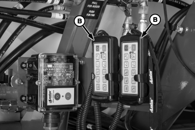
A82215-UN-04APR14A - Conveyance Control Valve
B - Conveyance Remote
Operate conveyance control valve (A), or conveyance remote (B) to fill tank. -
IMPORTANT: Do not illuminate the lights when seeding or transporting.
A82772-UN-12JUN14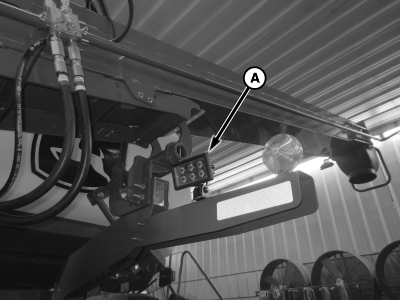
A82200-UN-01APR14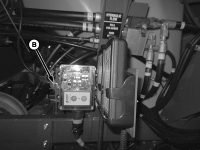
A82776-UN-13JUN14A - Field Lights
B - Field Light Switch
Field lights (A) are used only when filling the machine. Use switch (B) to turn lights on and off. -
NOTE:
A65089-UN-13AUG09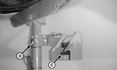
A46297-UN-19JUL00A - Lower Lights
B - Upper Lights
C - In-Tank Level Sensors
D - U-bolt
Tank fill lights display regardless of current monitor mode (SETUP, RUN, or INFO).NOTE: Amber indicator lights are dual purpose. The lights indicate tank fill status as described. In RUN mode, lights indicate fan speed, as described in the Air System section. Fan speed indicator lights are a setup feature, not an operational display.
Product level is also indicated on GreenStar™ display.
Observe the fill lights for indication of tank level. The lower (A) and upper (B) lights signal a full tank for the front or rear tank.
When all in-tank level sensors (C) are covered with product, the upper and lower lights alternately flash to indicate that the tank is full. Lights stop flashing if:
- More than three minutes have elapsed with no activity.
- There is activity at another tank (any sensor activated).
- Cart begins to move; tire speed sensed.
Adjust the top sensor for different products or when using a screen in the lid opening. To adjust the sensor assembly, loosen U-bolts (D).
-
IMPORTANT: To avoid inaccurate metering, ensure that tank lids are sealed tightly. Verify proper lid adjustment. (See Adjust Tank Lid Down Pressure And Centering Tabs in the Service section.)
A40148DS-UN-21OCT99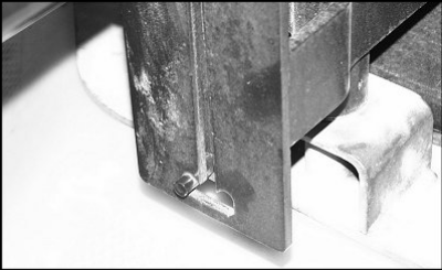
A43878-UN-09OCT99J-slot
A - Handle
After filling the tanks, perform the following steps to ensure proper lid seal:- Wipe product overflow from lid seal.
- Inspect lid seal for damage or product buildup.
- Rotate lid over opening until it contacts the stop.
- Verify that lid is not clamped down on lid centering brackets.
- To lock lid in J-slot, push handle (A) down.
|
GreenStar is a trademark of Deere & Company |
BB83525,00001A3-19-20141124 |