Agitator Installation, Activation, and Deactivation
 CAUTION: Chemicals are often used in agricultural applications
(fungicides, herbicides, insecticides, pesticides, rodenticides, and
fertilizers). Chemical residue remains inside air cart tanks. Always
follow all label directions for effective, safe, and legal use of
agricultural chemicals. Reduce risk of exposure and injury. Wear appropriate
personal protective equipment as recommended by the chemical manufacturer.
CAUTION: Chemicals are often used in agricultural applications
(fungicides, herbicides, insecticides, pesticides, rodenticides, and
fertilizers). Chemical residue remains inside air cart tanks. Always
follow all label directions for effective, safe, and legal use of
agricultural chemicals. Reduce risk of exposure and injury. Wear appropriate
personal protective equipment as recommended by the chemical manufacturer.
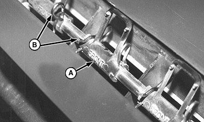
A47133-UN-14MAR01
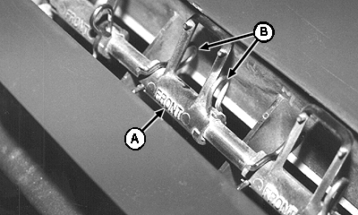
A - Agitators
B - Spring Pins
Install and activate agitators (A) above each active meter segment to keep product flowing freely.Deactivate agitators above inactive meter segments. Remove spring locking pins to deactivate.
Do not remove meter housing to service agitators. Tank must be empty to service agitators.
Two people are required to service agitators. One person outside the tank to slide shaft from housing and one person inside the tank to position and install agitators and spring pins.
-
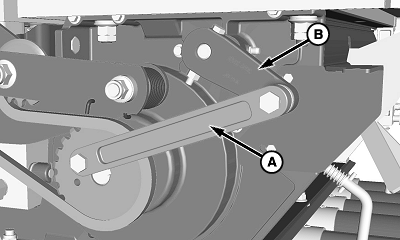
A70720-UN-16FEB11A - Drive Arm
B - Agitator Crank
Disconnect hydraulic hoses from tractor. -
Outside Person: Remove shield.
-
Disconnect drive arm (A) from agitator crank (B).
-
Remove hardware and crank arm from shaft. Remove and retain flat washers from end of shaft.
-
CAUTION: Do not enter tank unless another person is present
and hydraulic hoses are disconnected from tractor.
A42566-UN-05MAY98A - Spring Pins
Inside Person: Remove all existing spring pins (A) from shaft.NOTE: Meter housing shown removed from cart for clarity only.
-
A77463-UN-14MAR13A - Agitator Shaft
Outside Person: Slowly pull agitator shaft (A) from left-hand meter end cap.NOTE: The decal plate for half-width disconnect handles is installed on agitator shaft. Plate is removed when shaft is removed.
-
Inside Person: Collect existing agitators as shaft is removed.
-
A42568-UN-05MAY98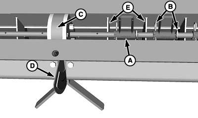
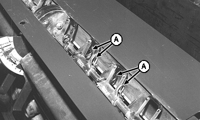
A60060-UN-11MAY07A - Agitators
B - Spring Pins
C - Center Support
D - Decal Plate
E - Half-Width Dividers
Outside Person: Slowly push agitator shaft back into position through left-hand end cap and half-width disconnect valve. -
IMPORTANT: The word “Front” (molded into agitator) must face front of machine.
Inside Person: Guide the shaft through center support (C) and half-width decal plate (D). As shaft is installed, install the same number of agitators (A) as active runs on each side of center support.
-
Position agitators over active segments and between half-width dividers (E).
-
Retain agitators with two spring pins (B).
-
A70720-UN-16FEB11A - Drive Arm
B - Agitator Crank
Outside Person: Install previously removed flat washers and crank arm (B). -
Attach drive arm (A) to crank.
-
Reinstall shield.
|
LD45720,0000635-19-20130314 |