Tow Hitch (Piton-Fix/Ball-Type)
NOTE: Components of the piton-fix/ball-type tow hitch that are subject to wear have to be checked every 250 hours (see “Service / Every 250 Hours”). Replace, if necessary.
Tow hitch (piton fix)

LX1041424-UN-10NOV06
A - Spring
B - Pin
C - Retainer
To attach an implement, pull up spring (A) and slide pin (B) to the right. Retainer (C) is forced upwards by a spring. Once the implement is attached, push retainer (C) down and slide pin (B) all the way to the left. Move spring (A) back down to its locked position (the position shown in the illustration).
Ball-type tow hitch

LX1049992-UN-27JUL11

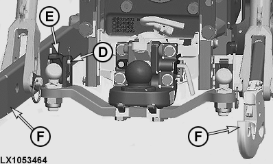
LX1053464-UN-29JAN13
A - Handle
B - Set Screw
C - Retainer
D - Locking Pin
E - Retainer
F - Draft Links
IMPORTANT: If there is a ball-type tow hitch with forced steering system on one side or on both sides, comply with the following:
• Before attaching implements, it is essential to remove the ball-type tow hitch and forced steering system.
• Before hitching trailers with forced steering, it is essential to remove the draft links (F).
For attaching an implement, pull handle (A) upward and slide to the right. This will open the locking device and retainer (C) can be moved upwards. After attaching the implement, push down retainer (C) and engage handle (A) in its initial position. Handle (A) will only engage properly when the locking pin is pushed all the way to the left. If necessary, use an 8 mm (0.3 in.) hex. socket key to adjust the set screw (B) on the retainer to make space for the eyelet of the trailed implement. Then tighten the locknut to 300 Nm (220 lb.-ft.) using a 30 mm (1.2 in.) wrench.
To attach the forced steering system, pull locking pin (D), lift retainer (E) and engage the forced steering system linkage. Then return retainer (E) and locking pin (D) to their initial positions.
Replace with a drawbar

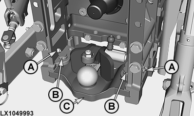
LX1049993-UN-27JUL11
A - Locking Pin
B - Retaining Pin
C - Support
The piton-fix tow hitch or the ball-type tow-hitch can easily be removed, e.g. to install a drawbar. Pull out locking pins (A), take out retaining pins (B) and pull support (C) out to the rear.
|
OULXBER,0001AB0-19-20130129 |