Front Hitch (Premium)
Depending on how the tractor is equipped, the front hitch can be operated from a front-hitch control lever or from the multi-function lever.
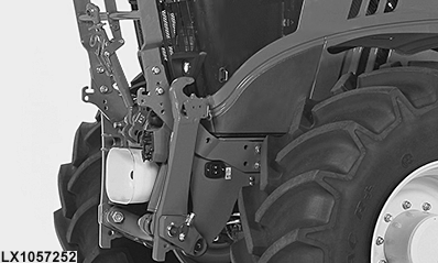
LX1057252-UN-10SEP13
Draft link, hook latch
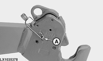
LX1035378-UN-18JAN05
A — Lock Parts Kit
 CAUTION: When installing devices with asymmetrical loads (e.g.
side boom mower decks) or when driving through high vegetation, or
carrying out forest work, the draft link hook must be secured against
being opened unintentionally.
Use John Deere™ AL165485 lock parts kit at both of the coupler hooks.
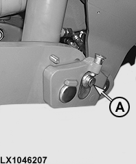
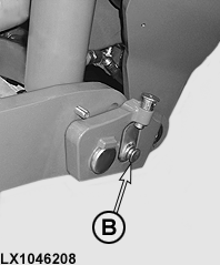
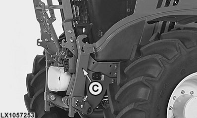
Draft link positions
LX1046207-UN-21JUN11
LX1046208-UN-21JUN11
LX1057253-UN-10SEP13
B — Draft links locked
C — Draft links in transport position
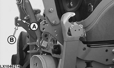
Brackets for mower deck springs (if equipped)
LX1046214-UN-22JUN11
A — Opening for chain
B — Bore for spring
Opening (A) allows attachment of the chain for cutting height limit.
NOTE: Move the SCV for lowering the mower deck to its float position.
The spring for dampening can be hooked into bore (B).
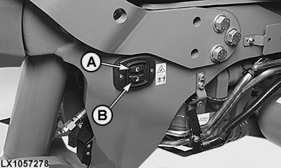
Remote Control
LX1057278-UN-11SEP13
For safety reasons, the hitch rises and drops at a slower rate.
With buttons (A) and (B), the front hitch can be raised or lowered. The limits set for the lifting height or operating depth is not taken into account.
Push upper switch (A) - Lift implement
Push lower switch (B) - Lower implement
NOTE: The remote control overrides the control lever in the cab.
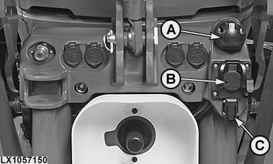
Front Sockets
LX1057150-UN-06SEP13
NOTE: Illustration shows tractor with additional equipment.
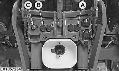
A — Seven-terminal power outlet socket
The socket is used to connect lights, flashers and electrical devices installed on the implement. Always use auxiliary light on towed implement when tractor signals and other lights are obscured.
NOTE: Suitable connectors can be obtained from your John Deere dealer.
B — ISOBUS socket (ISB)
An implement meeting ISO Standard 11783 may be connected at socket (B).
C — 3-terminal power outlet socket
Terminal 15/30 of the 3-terminal power outlet socket provides
a max. permanent direct current of 25 amps. Terminal 82 provides a
max. permanent direct current of 5 amps. Terminal 31 is ground.
Turn key in key switch to the right to supply power to terminal
82. Terminal 15/30 is supplied with power even when the ignition is
switched off.
IMPORTANT: When operating electrical consumers with high current consumption, the maximum permitted current load of the supply circuit (25 amp) must not be exceeded.
Front couplers
LX1057254-UN-10SEP13
LX266797-UN-18MAR16
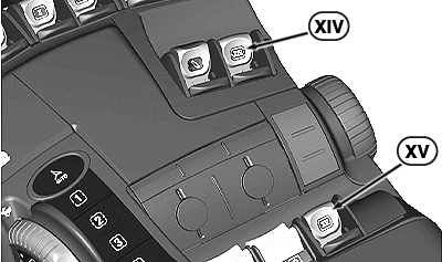
A — Couplers, Selective Control Valve XIV
B — Couplers, Selective Control Valve XV (optional)
Couplers (A) and (B) are actuated by means of the control levers of selective control valve XIV and XV.
NOTE: Use couplers (A) of selective control valve XV only for ancillary functions.
CAUTION: The hydraulic system has a maximum stand-by pressure
of 20000 kPa (200 bar; 2900 psi). For your own protection and to assure
proper functioning of the system, use only genuine John Deere parts.
Couplers (A) and (B) allow hydraulic hose to be connected and disconnected only if no pressure is present.
To connect the hose union, press it firmly into the coupler.
To disconnect the hose, give it a firm pull.
C — Pressure-Free Return Circuit
This connection ensures pressure-free oil return.
Controls
LX1057279-UN-23JAN14
LX266798-UN-18MAR16
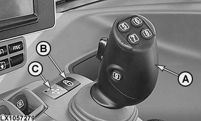
A - Multi-Function Lever
B - Lock Button, Multi-Function Lever ON/OFF
C - Indicator Light, Multi-Function Lever Enabled
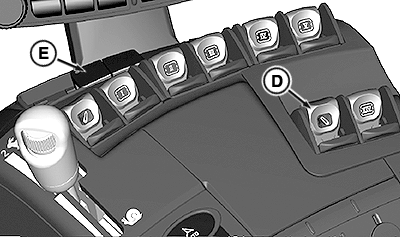
D - Control Lever, Front Hitch
E - Lock Button, Selective Control Valves ON/OFF
The front hitch is supplied with oil through selective control valve X. The front hitch is controlled by means of the multi-function lever (A) or with the control lever (D) of the front hitch.
IMPORTANT: When the front hitch is not in use, the multi-function lever (A) or control lever (D) has to be locked. To do so, press lock button (B) and make sure that the indicator light (C) or (E) of the lock button is lit. The multi-function lever or control lever can still be moved, but the front hitch should not move. Otherwise there is risk of the front hitch being actuated unintentionally, which could cause severe accidents.
Safety
CAUTION: It is important to observe the maximum permissible
axle loads and the load capacity of the tires when using the front
hitch.
CAUTION: A front-mounted implement adversely affects the driving
characteristics of the tractor. Adjust vehicle handling to the change
in driving dynamics of the tractor.
CAUTION: Always lower front-mounted implements to the ground
when the tractor is left unattended.
CAUTION: Lower front-mounted implement to the ground and stop
the engine before connecting the implement to one of the front quick
couplers.
CAUTION: Always bear in mind that the dimensions of the tractor
front have changed, especially when leaving the farm or the fields
and on roads and junctions. If in doubt, ask for a second person to
assist.
CAUTION: Comply with lighting requirements. Headlights and turn
signals may be concealed by the front-mounted implement. In this case,
use additional lighting.
CAUTION: When the front hitch is not in use, the draft links
should always be folded up.
|
OULXA64,000309A-19-20160318 |