Hydraulic Pick-Up Hitch (Mechanically Actuated)
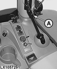
LX1057291-UN-12SEP13
Side Console
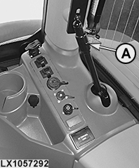
LX1057292-UN-12SEP13
CommandARM™
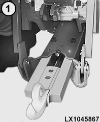
LX1045867-UN-15FEB11
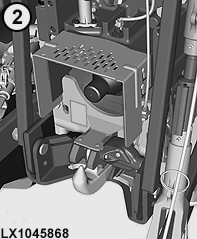
LX1045868-UN-15FEB11
A - Release Lever
1 - Hitch in Position for Attaching Trailer
2 - Hitch in Stored Position
This type of hitch can be operated using the hitch controls and one selective control valve.
-
Raise draft links to maximum height and use SCV to retract the hitch hook fully.
-
Pull release lever (A) and lower the draft links. Hold the release lever until the hitch hook has moved from the stored position (lever remains in open position).
-
Extend the hitch hook fully by actuating the selective control valve.
-
Lower draft links/hitch hook to desired height.
-
Raise the draft links so that the hitch hook engages in the towing eye of the implement, then fully raise the pick-up hitch.
-
Retract the hitch hook fully by means of selective control valve until it is fully locked (lever A returns to its starting position).
-
Lower the draft links.
-
Check that the hitch is locked correctly. If this is the case, it will not lower when the draft links are lowered and not extend when the selective control valve is operated.
IMPORTANT: If the release lever is hard to operate or locking the hitch hook is not performed automatically (step 2 or step 6 above), have your John Deere dealer check the setting of the lift links or of the pick-up hitch hook.
 CAUTION:
LX1045869-UN-15FEB11
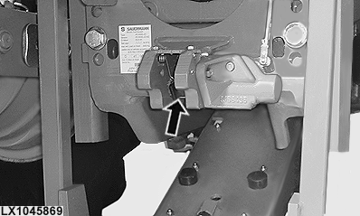
With the hitch lowered, NEVER reach into the receiver opening (see arrow). Risk of injury!
NOTE: Pick-up hitch components that are subject to wear can be checked during regular service work. See relevant "Service" section. Replace, if necessary.
Maximum permissible static vertical loads and towable loads are stated in the Specifications section.
LX1045870-UN-15FEB11
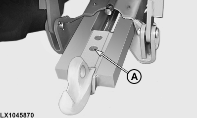
The part not required can be stored in a holder on the side-frame.
|
OULXA64,00030D1-19-20140820 |