CAT II Drawbar
The drawbar is used to pull drawn equipment of all types, particularly PTO-driven implements. The drawbar is located to increase the rear axle load and slightly reduce load on the front axle.
Besides having a variable swinging range, the drawbar can also be adjusted lengthwise. Maximum permissible static vertical loads and towed loads are stated in "Loads and Weights" in Section 500A.
LX364410-UN-27JUN19
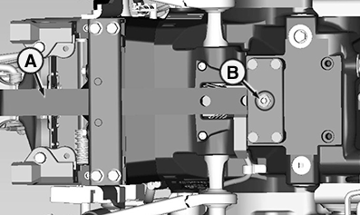
CAT II Drawbar
A - Drawbar
B - Hex Stopper (1 used), 310 N·m (230 lb-ft)
Drawbar (A) can be set to the following lengths:
|
CAT II .............. |
250 mm |
350 mm |
400 mm |
|
9.8 in. |
13.8 in. |
15.7 in. |
These lengths determine the distance from the end of the PTO shaft to the attachment point of the drawbar.
To adjust, remove hex stopper (B) and pull out pin. Shift drawbar (A) and align the holes so that they line up with each other. Then insert the pin, screw on hex stopper (B) again, and tighten to the prescribed torque.
NOTE: Drawbar components that are subject to wear can be checked in the course of maintenance work. See Section 220D. Replace, if necessary.
NOTE: Towing on public roads with the drawbar set to one side is not permitted!
|
OULXBER,0002C93-19-20190627 |